
Humidity Control Switch Circuit

The humidity-controlled switch circuit employs a humidity sensor to detect changes in moisture levels in the environment. The sensor typically used is a capacitive or resistive humidity sensor, which outputs a voltage or resistance that varies with the humidity level. This output is fed into a comparator circuit, which compares the sensor output against a predefined reference voltage.
When the humidity level exceeds a certain threshold, the comparator output changes state, triggering a control mechanism. This mechanism can be a relay or a transistor, which then connects or disconnects the electrical load from the power source. For example, if the humidity level rises above the set point, the relay activates, turning on the heater to increase the temperature and reduce humidity. Conversely, when the humidity drops below the set point, the relay deactivates, turning off the heater.
The circuit may include additional components such as a potentiometer to adjust the humidity threshold, an LED indicator to show the operational status, and protection diodes to safeguard against voltage spikes. Power supply considerations must also be accounted for, ensuring that the circuit operates within its specified voltage range.
Overall, this humidity-controlled switch circuit is an effective solution for managing humidity levels in various applications, ensuring optimal comfort and preventing damage from excessive moisture.This humidity controlled switch circuit turns on and off an electrical load (for example a heater) depending on the moisture content of the surrounding air.. 🔗 External reference
Related Circuits
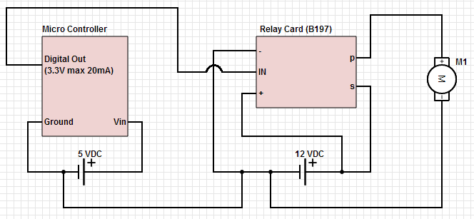
The objective is to control a 12 VDC device (on/off) from a microcontroller using a relay card. The relay requires a 12 VDC operating power supply. To achieve the control of a 12 VDC device using a microcontroller and a...
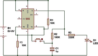
The circuit functions as a toggle switch, exhibiting two stable states: ON and OFF. When the circuit is in the ON state, it remains in that state until the switch is pressed again. The project is based on a...
This circuit prioritizes a microphone and preamplifier (voice circuit) over any other audio signal, functioning similarly to a one-way intercom. When the push-to-talk switch is activated, the main amplifier switches from music to the voice signal. Essentially, a voice-over...
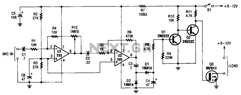
The audio-controlled switch utilizes a pair of 741 operational amplifiers, two 2N2222 general-purpose transistors, a hexFET, and several supporting components to create a circuit capable of activating devices such as a tape recorder, a transmitter, or virtually any other...
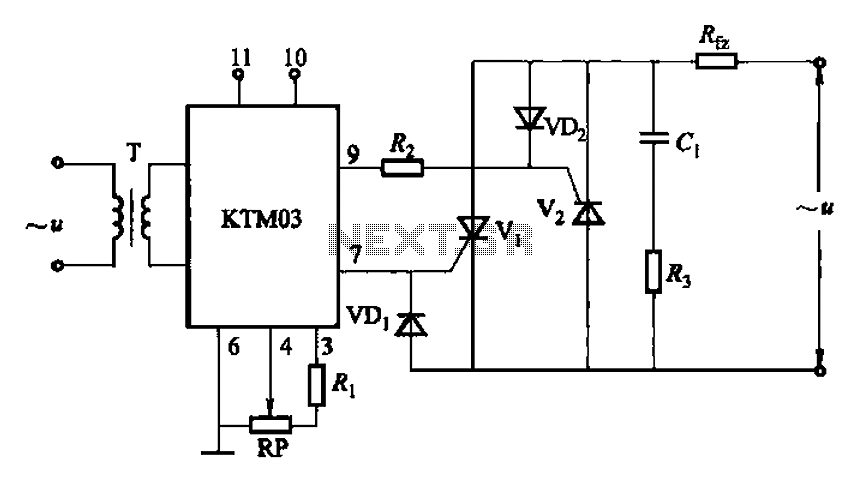
Adjustment potentiometer RP can modify the conduction angle of thyristor Vl, vz, thus altering the voltage applied across the load Rfz. The adjustment potentiometer (RP) serves a critical role in controlling the conduction angle of the thyristors Vl and vz within...
This weblog discusses electronic circuit schematics, PCB design, DIY kits, and electronic project diagrams. The 1K resistors in the circuit are significant as they allow the LEDs to activate at different audio levels. While these resistors can be modified,...