
Versatile Multifunction Circuit Uses Only Three Inverters

This circuit design effectively utilizes inverters to create versatile applications, allowing for multiple configurations depending on the input signal characteristics. The incorporation of regenerative feedback ensures that the circuit maintains its state until explicitly reset, providing stability in its operation. The timing components, specifically R3, R4, and C1, play crucial roles in defining the output characteristics, including pulse width and duty cycle, which can be tailored to specific application requirements.
When used as an astable multivibrator, the circuit continuously oscillates, producing a square wave output. The frequency of oscillation is determined by the values of the resistors and capacitor in the timing network. In contrast, when configured as a monostable multivibrator, the circuit generates a single pulse in response to a triggering input, making it suitable for applications such as switch debouncing or generating reset signals.
The addition of steering diodes allows for modulation of the duty cycle, enabling more complex waveform generation. The careful selection of resistor and capacitor values can achieve desired timing characteristics, facilitating a range of applications from audio signal generation to precise timing functions in digital circuits.
Overall, the circuit's flexibility and adaptability make it a valuable component in various electronic designs, capable of fulfilling multiple roles with minimal additional components.The versatile circuit shown can be used to realize several different circuit functions ”an astable multivibrator, a monostable multivibrator, a switch debouncer, or a frequency discriminator ( Fig. 1 ). Inverters U1a and U1b are connected as a latch. When the input voltage (VIN) is high, the output voltage (VOUT) will go high. Due to the regenera tive feedback through resistor R2, VOUT will remain high until a reset condition occurs or power is removed. While VOUT is high, capacitor C1 is charged through R3. The output voltage of inverter U1c is high until the voltage on C1 exceeds the high threshold (VTH) of U1c.
At this time, the output voltage of U1c will go low. A low voltage at the output of U1c will reset the latch through diode D1. With the latch reset, VOUT will be low and C1 will discharge through R3. When the voltage on C1 goes below the low threshold (Vt1) of U1c, it`s output voltage will go high. The circuit is now back to it`s original state. This circuit has a natural period (T= t1 + t2) consisting of a high output that lasts for t1 seconds and a low output that lasts for t2 seconds ( Fig. 2 ). During the entire time period T, the circuit can not be retriggered. The output pulse width (t1) is determined as follows: Referring to Figure 1, if VIN is a signal having a period TIN that`s larger than T, VOUT will be a pulse train.
In this case, VOUT will have a period equal to TIN and a pulse width equal to t1. The duty cycle of VOUT can therefore be adjusted by changing TIN. In the case where VIN has a period TIN that`s much shorter than T, the circuit will continuously oscillate with period T. If T is in the audible range and used to drive a speaker, some unique sounds can be generated depending on TIN.
During its natural period T, the circuit won`t respond to any input. An effective switch debounce function can be achieved by making T longer than the switch bounce time. The same characteristics make the circuit useful for generating a reset pulse. Connecting VIN to VDD will cause the circuit to function as an astable multivibrator with an output period of T.
Connecting VIN to a signal that is high for a time longer than T creates a gated astable multivibrator. The number of pulses generated will depend on how long VIN is high compared to T. To customize the duty cycle of VOUT, steering diodes and a second resistor can be added, as shown in Figure 3.
For the circuit in Figure 3, t1 is calculated using R3C1 in the time constant. To calculate t2, R4C1 is used. The duty cycle is defined as: 🔗 External reference
Related Circuits

UPDATED 2014 This project presents the original high-power mobile phone jammer circuit, with all updates posted here. Caution is advised regarding the use of this device, as it is illegal. The purpose of sharing this circuit is solely for...
The MP3 files (up to 65,536) are stored on a micro SD card. This embedded MP3 module is a universal and compact circuit (37 mm x 27 mm) designed for playing MP3 audio files. The MP3 module can be...
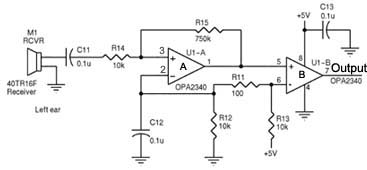
Assistance is required regarding the circuits provided below. The focus is on an ultrasonic receiver circuit that utilizes two ultrasonic components. The ultrasonic receiver circuit is designed to detect ultrasonic waves, typically in the frequency range of 20 kHz to...
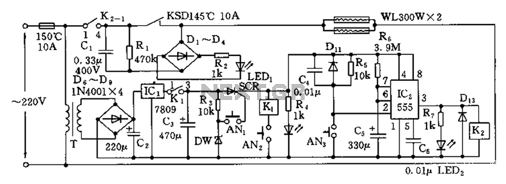
The disinfection cabinet circuit operates on the principle of using infrared heating within a closed cabinet to create a high-temperature environment for disinfecting tableware. The circuit includes an AC buck regulator, an infrared heating circuit, and a timing control...
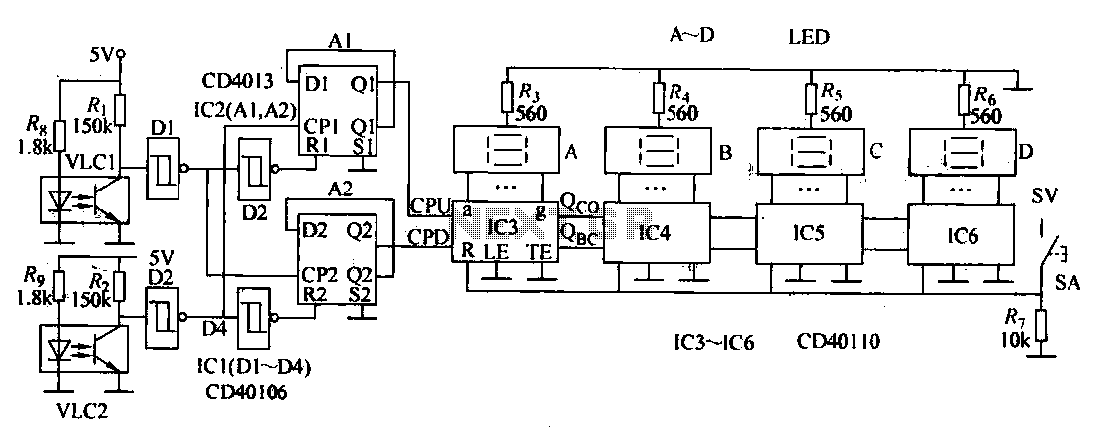
This document describes an electronic winding machine with manual, electric, and semi-automatic features. The specific example highlighted includes an electronic counting function that assists users in managing motor windings. The circuit design consists of various components as illustrated in...
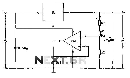
The circuit consists of resistors R1, R2, and RP, where the resistance values play a critical role in determining the magnitude of the current I. This current must exceed the input current of the operational amplifier, which is approximately...