
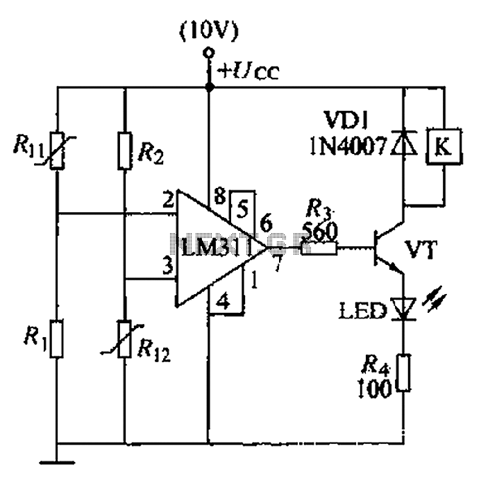
Adjustable output voltage regulator circuit diagram

The described circuit utilizes resistors R1, R2, and RP to regulate current flow, ensuring that the operational amplifier operates within its specified parameters. The current I, which is crucial for the amplifier's performance, must exceed 1mA to maintain functionality. The output voltage plays a significant role in this relationship; as the output voltage approaches its maximum, the necessary current I must also increase to match this requirement.
Resistor R1's value is particularly important, as it must be greater than 0.5V to provide stability to the operational amplifier's low output voltage. This stability is vital for the proper functioning of the circuit, especially when dealing with low voltage outputs. The minimum output voltage is influenced by the voltage across UR1 and the voltage from the integrated voltage regulator (UR). This ensures that the circuit maintains a consistent output even under varying load conditions.
The maximum output voltage is determined by the configuration of the circuit, specifically by the relationship between the supply voltage (Us) and the voltage across R2 (UR2). In the provided example, with Us set to 1.5V and UR2 at 1V, the maximum output voltage is calculated to be -2.5V. This indicates the circuit's ability to handle negative voltages, which may be necessary for certain applications.
In summary, this circuit design emphasizes the importance of resistor values and their impact on current and voltage regulation within an operational amplifier setup. Proper selection and configuration of these components are essential for achieving the desired performance and stability of the circuit.Circuit R1 R2 + RP + size branch resistance value determines the magnitude of the current I, the current should be greater than the input current of the operational amplifier, is about I = 1mA. It depends on the output voltage as low as UAmin. Therefore, when the output voltage is adjusted to the maximum value of the current I should be correspondingly larger. Resistor R1 value should be greater than the operating range of the R1 voltage 0.5V, in order to stabilize the op amp's low output voltage.
Minimum output voltage is determined by UR1 + UR, UR integrated voltage regulator constant voltage. The maximum output voltage is determined by UeX (-Us + UR2). If Us = 1.5V, UR2 = 1V, then Umax FUe = -2.5V.
Related Circuits
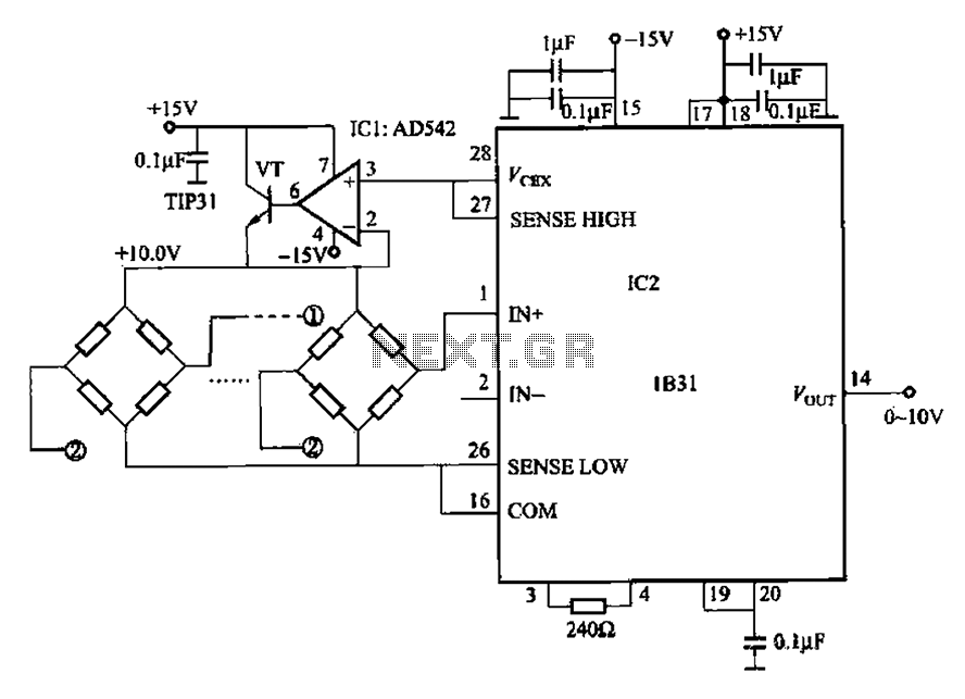
The 1832 low drift input has a temperature coefficient of 0.07 µV/°C (RTI, G 500) and exhibits excellent linearity with a maximum deviation of 0.005%. It can drive resistive loads greater than 120 ohms in a bridge excitation circuit,...
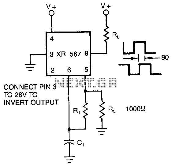
The XR-567 operates as a precision oscillator, providing two distinct square-wave outputs at pins 5 and 8, which are nearly in quadrature phase with one another. Due to the internal biasing configuration, the typical phase shift between the two...
Here is an updated schematic featuring the RF Solutions receiver along with several minor additions. The design includes additional circuitry to manage the signals effectively. The updated schematic incorporates an RF Solutions receiver, which is essential for receiving radio frequency...
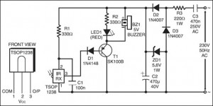
The following circuit illustrates an IR Remote Control Tester Circuit. Features include that transistor T1 conducts during the negative pulse period, and there is a data output pin. The IR Remote Control Tester Circuit is designed to verify the functionality...
A boiler control circuit is designed to regulate the temperature of water in a hot water heating system. This circuit typically utilizes a comparator's comparison function to manage the heating equipment. The circuit includes a thermistor that forms a...
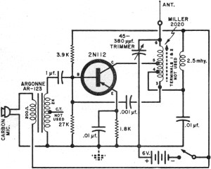
It had been a little over a decade since the invention of the transistor when this article appeared in the August 1959 edition of Popular Electronics. Transistors were still a mystery to many, including engineers, technicians, and hobbyists. Author...