
Versatile Op Amps Need No Resistors

The design of a switching power supply capable of operating across a wide range of input voltages is crucial for meeting diverse market needs. The forward mode switching power supply typically limits operation to specific voltage ranges, which can be restrictive in global applications. The introduction of boost mode converters has expanded the operational range, yet they still fall short when faced with higher voltage requirements.
To address these limitations, a discontinuous mode flyback converter is proposed, which offers a significant advantage by extending its operational input voltage range from the conventional 3:1 to an impressive 6:1. This is particularly beneficial for applications where power supply devices must adapt to varying voltage standards across different regions, including both residential and industrial sectors.
The key to achieving this extended range lies in modifying the operational mode of the flyback converter. This alteration allows for more flexible voltage handling without sacrificing the reliability that is essential for power supply applications. Furthermore, the integration of advanced Power MOSFETs with high breakdown voltage ratings of 1,200 V enables the converter to withstand higher input voltages safely. This development not only enhances the versatility of the power supply design but also reduces the need for multiple product variations tailored to specific voltage ranges, ultimately leading to cost savings and improved customer satisfaction.
In conclusion, the proposed approach for the discontinuous mode flyback converter represents a significant advancement in power supply design, facilitating operation across a broader voltage spectrum while maintaining operational integrity. This innovation is essential for manufacturers aiming to compete in an increasingly globalized market, where adaptability and reliability are paramount.One of the many problems besetting the power supply designer today is being able to design a switching power supply that is able to operate in all the power systems within their international marketplaces. Forward ’mode switching power supplies typically operate over a single power system`s range of voltage, that is, 90 to 130 VAC or 200 to 270 V
AC. Boost ’mode converters CAN just make the range of 90 to 270 VAC. Any higher input voltages would then require a different design. This leads companies to create products targeted at specific marketplaces, which CAN be costly, or to have their customers arrange jumpers to accommodate their power system which CAN be annoying or lead to costly errors. Added to this are those industrial companies which may not only have their products reside on residential power systems but also have the varied international industrial power systems.
This means that a single product family might have to operate from an input voltage of 90 to 600 VAC, well beyond the residential limits of 90 to 270 VAC. This paper reviews one method of enabling a discontinuous ’mode flyback converter to operate beyond its traditional range of input voltage of 3:1 to a range of more than 6.
6:1 without affecting the reliability of its operation. This is done by changing its mode of operation and the use of recently available Power MOSFETs with breakdown voltage ratings of 1, 200 V. 🔗 External reference
Related Circuits
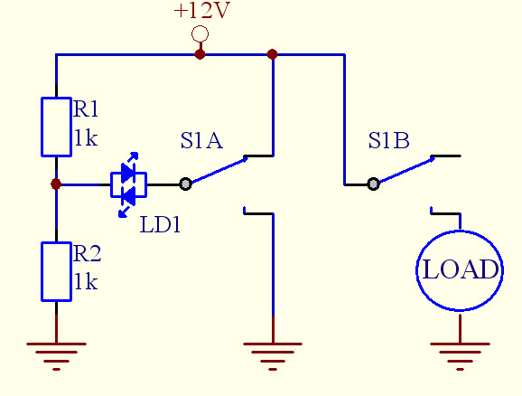
Assistance is needed for a project involving the construction of a switch panel. The individual has a good understanding of 12V electrical wiring but is encountering difficulties with this specific task. The project involves designing a switch panel that can...
An LED, or Light Emitting Diode, is a semiconductor device that allows current to flow in one direction while blocking it in the opposite direction. This characteristic makes LEDs polarized components, having a positive side known as the anode...
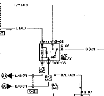
An automotive relay is being analyzed, which exhibits a more complex wiring configuration than typical relays. The diagram indicates that the B/G line maintains a high signal if certain conditions are met, specifically when the engine temperature is excessively...

The versatile circuit can be employed to achieve various functions, including an astable multivibrator, a monostable multivibrator, a switch debouncer, or a frequency discriminator. Inverters U1a and U1b are configured as a latch. When the input voltage (VIN) is...
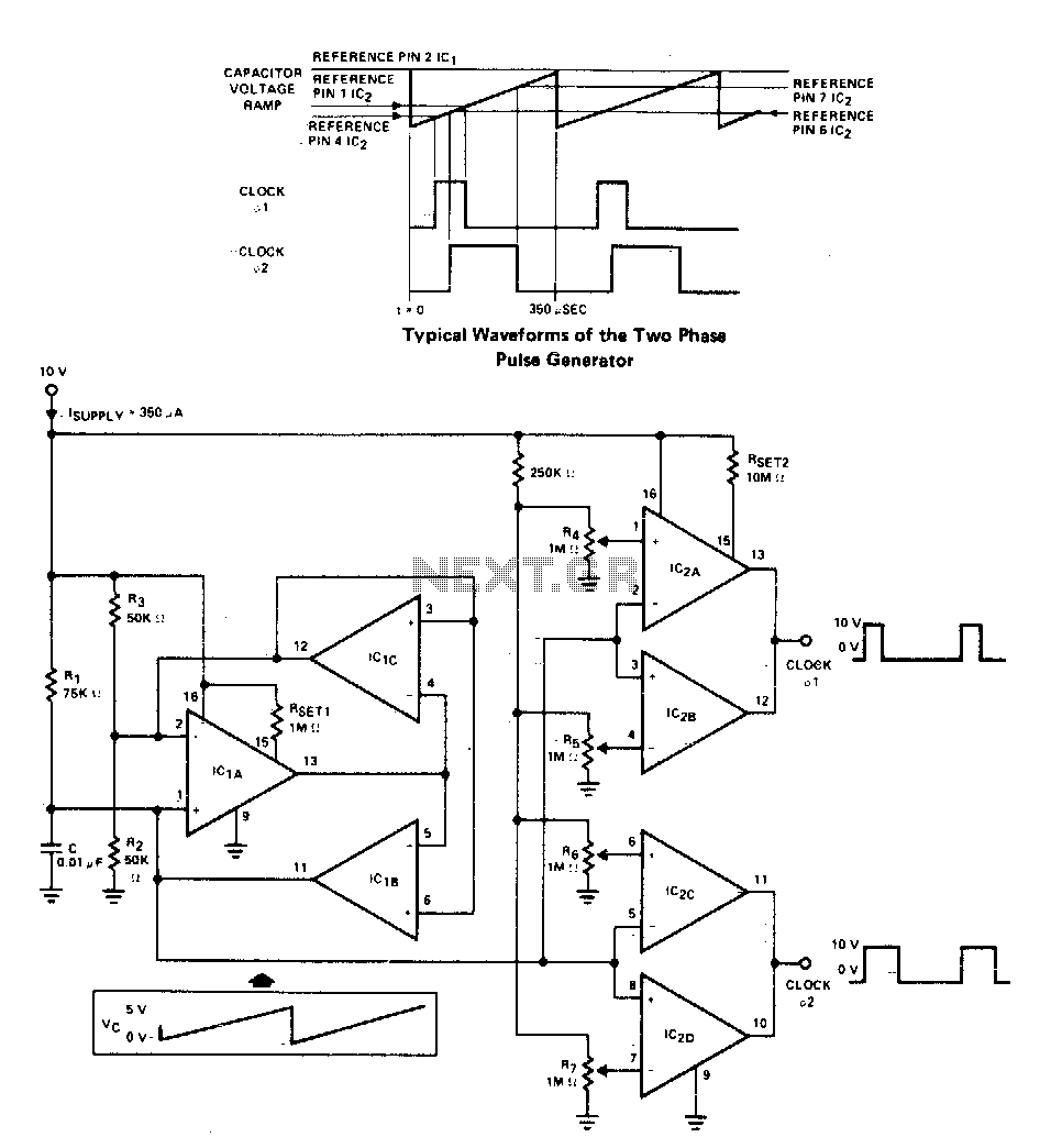
A two-phase clock generator utilizes two L161 integrated circuits to produce pulses with adjustable widths and phase relationships. Additionally, a ramp generator supplies input to two variable window comparators, which are configured using IC2A-IC2B and IC2C-IC2D, respectively. The two-phase clock...
Assistance is required regarding the circuits provided below. The focus is on an ultrasonic receiver circuit that utilizes two ultrasonic components. The ultrasonic receiver circuit is designed to detect ultrasonic waves, typically in the frequency range of 20 kHz to...