
Very Simple Telephone Intercom Circuit Circuit

This intercom circuit allows for communication between two telephones, specifically older rotary models, which do not require electronic components for operation. The circuit is designed to function primarily with the mechanical aspects of these telephones, leveraging their inherent capabilities to establish a two-way communication link.
The setup involves connecting the two handsets in a parallel configuration, ensuring that each phone's ringer and speaker are properly integrated into the circuit. A power source, typically a low-voltage DC supply, is necessary to energize the handsets. The circuit may include a simple resistor-capacitor (RC) network to filter any noise and stabilize the power supply, ensuring clear audio transmission.
For optimal performance, the circuit should be housed in a protective enclosure to prevent accidental disconnection or damage. The use of twisted-pair wiring is recommended to minimize electromagnetic interference, which can degrade audio quality.
In summary, this intercom circuit provides a practical solution for utilizing older rotary telephones as a communication system, emphasizing simplicity and reliability while requiring minimal electronic components. Two telephones can be used as an intercom by using this circuit. Older style rotary phones that are nonelectronic might work best in this application. Also, handsets only might be powered this way.
Related Circuits
This page features H-Bridge circuits used for controlling direct current motors. Several designs are shown using both CMOS and Bi-Polar power devices. These circuits could be used as the basis for Model Railroad DCC Boosters or PWM motor controllers....
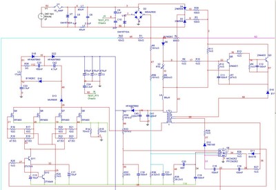
A Power Factor Correction (PFC) board has been obtained from an old Sun Microsystems Spark450 power supply (part number 300-1359-xx). This board contains all necessary components for a 650-watt inverter. However, the complete PFC circuit is not fully detailed...
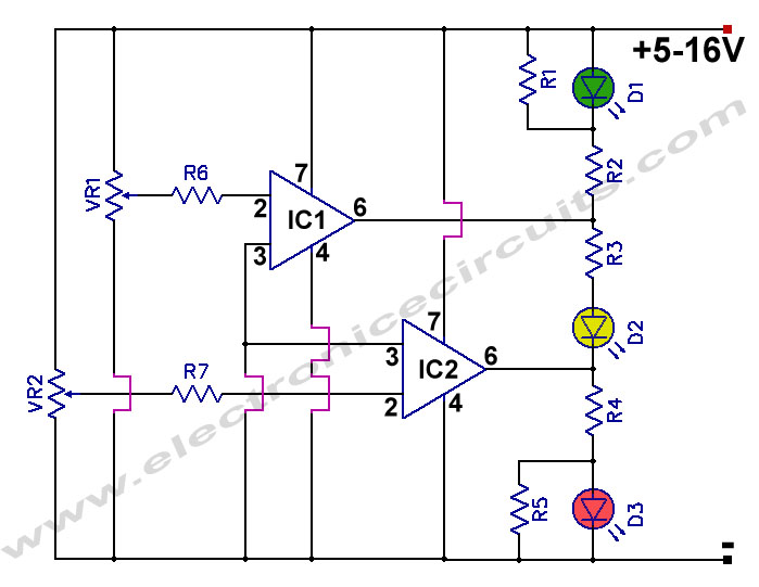
12V Battery Charge Nominal Discharge (Low) Indicator Circuit. This circuit monitors car battery voltage and provides an indication of nominal levels. The 12V Battery Charge Nominal Discharge Indicator Circuit is designed to monitor the voltage levels of a car battery...
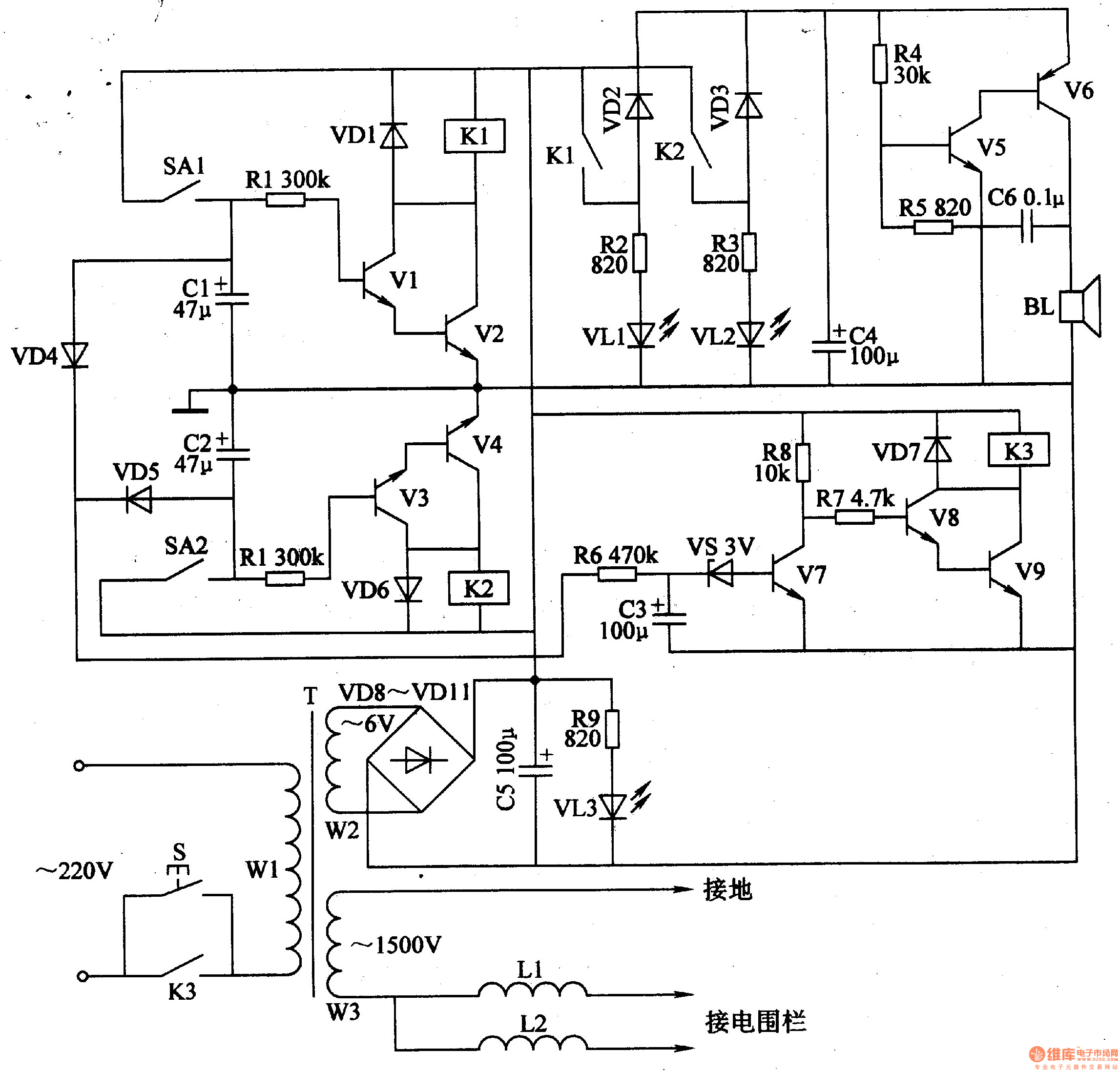
The electric fence control circuit includes a +6 V power supply circuit, a high-voltage output circuit, a trigger control circuit, an alarm circuit, and a protection circuit. The +6 V power supply circuit consists of a power control button...
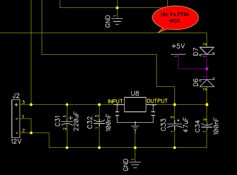
When only the voltage regulator (VR) supplies power to the circuit, the microcontroller unit (MCU) will receive power from the +5V bus, while the FTDI chip will only receive VCCIO. At the midpoint of the voltage divider formed by...
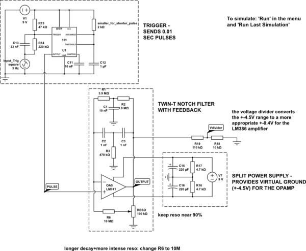
The circuit is constructed on a breadboard and produces the expected sound characteristics, specifically a damped sine wave reminiscent of large 808/909-style kicks. However, it exhibits a significant amount of noise. An attempt was made to mitigate this by...