
VGA to TV converter

The circuit is relatively straightforward, as the RGB signal output from the VGA card is already standardized at 0.7 Vpp for a 75-ohm load. The RGB plus composite video format is the necessary signal format for the TV input. Additionally, a specialized driver is required to set the VGA card to a suitable refresh rate for standard television. To combine the sync signals, the circuit utilizes a TTL chip with four XOR gates, along with two resistors and two capacitors. The choice of a TTL chip is logical, given that VGA sync signals are at TTL levels. The sync signal combiner is designed to adjust to varying sync polarities, ensuring the correct composite sync signals are generated. The VGA card employs different sync signal polarities to indicate the resolution being used, and this circuit can adapt to these changes in less than 200 milliseconds—faster than the display mode change of a typical VGA monitor.
Constructing a VGA to TV converter is relatively easy for those with experience in electronic circuit assembly. The circuit can be built on a small piece of veroboard, eliminating the need for a specialized circuit board. A well-stabilized +5V power source is required, with the actual voltage acceptable in the range of 4.75V to 5.25V. The circuit consumes less than 150 mA, thus a large power supply is unnecessary. If a suitable power source is not available, a small general-purpose wall transformer and a voltage regulation circuit can be utilized. If the computer graphics card is VESA DDC compliant, it may provide +5V at VGA connector pin 9, although this is not guaranteed. Testing for this +5V output can be easily performed with a multimeter. For systems lacking this power output, alternative power sourcing methods can be explored through additional resources.
The construction of the adapter typically involves a small circuit board, designed collaboratively by the author and Aki Suihkonen. A scanned image of the PCB, viewed from the component side, is available for reference. For those wishing to create a simple one-sided circuit board, downloadable images of both the copper side and component side views are provided. The PCB image is scanned at a resolution of 300x300 dots per inch, and users are advised to utilize appropriate image viewing or editing software to print it at the correct scale of 4.09 x 2.24 inches, as printing directly from a web browser may not yield usable results. The component side view of the PCB is particularly useful for those employing photographic methods or heat transfer methods for circuit board fabrication.Here is the circuit for VGA to scart connection. It is basically a circuit which takes VGA signals and converts it to RGB + composite sync signal which can be fed to TV via SCART connector. VGA card picture components RED, GREEN and BLUE are already at the correct voltage level (0. 7Vpp) and has correct impedance (75 ohm) for direct connection to c orrespondign inputs in the TV. What needs to be done is to combine separate horizonal and vertical sync signal from VGA card to one composite sync signal which is feed to TV video in pin in SCART connector. This sync signal conversion is done by the electronics in the circuit. The circuit has also sends correct level signal to the TV RGB input enabling control pin in the SCART connector (pin 16).
This circuit is designed for converting normal VGA signals standard RGB signals and composite sync signal. The circuit is quite simple, because RGB signal ouput from VGA card is already standard 0. 7Vpp to 75 ohm load. RGB+composite video format is the signal format needed by the TV input. Besides that format conversion special drivers is needed to set the VGA card to suitable refresh rate for normal TV.
For sync signals there is a circuit which combines horizonal and vertical sync signals to from composite sync singals. The circuit is simply based on one TTL chip with four XOR ports, two resistors and two capacitors. TTL chip was logical choise because VGA sync signals are TTL level signals. The sync signal combiner has a system to adjust to different sync polarities so that it always makes correct composite sync signals.
VGA card uses different sync signal polarities to tell the monitor which resolution is used. This circuit adjusts to sync signal polarity changes in less than 200 milliseconds, which is faster than setting time of a normal VGA monitor in the display mode change. VGA to TV converter is quite easy to build if you have some experience in building electronic circuits.
The electronics of the circuits can be easily built to a small piece of veroboard and no special circuit board is needed. I used this approach in my prototype. The circuit need well-stabilized power +5V power source (actual voltage can be in 4. 75V to 5. 25V range). The circuit takes less than 150 mA current, so you don`t need a large power supply. If you don`t have anythign suitable avalable, you can always use a small general purpose wall transformer and a small +5V voltage regulation circuit.
If your computer graphics card is VESA DDC compliant, it might have +5V available at VGA connector pin 9 (the standard have option that VGA card can have +5V at pin 9, but it does not necessarily have to have this). You can test easily if your computer has this +5V output using multimeter. If your VGA card does not have power ooutput, then check my How to get power from PC to your circuits article for more ideas.
I have built most of adapters I have made to a small circuit board which is designed by me and Aki Suihkonen. You can see as small picture of the PCB in the picture below (copper traces viewed from component side): If you want to make this simple one side circuit board then download either the copper sive view or component side view whichever suits your use better.
The circuit board picture here is a scanned version (scanned at 300x300 dots/inc resolution) of the actual circuit board (version 1. 0) in GIF format (size of picture is 1227x672 pixels). You need to use suitable image viewing/exiting program to print it in correct resolution so that you get a picture with size of 4.
09x2. 24 inches (you can`t get anything useful by printing from your web browser). Component side view of the PCB is very useful if you hare making the circuit using photographic method (turn the slide you just printed around and use it as the PC master film for exposure) or if you use heat transfer method (just print the file to a special meterial which allows transfer of ton 🔗 External reference
Related Circuits
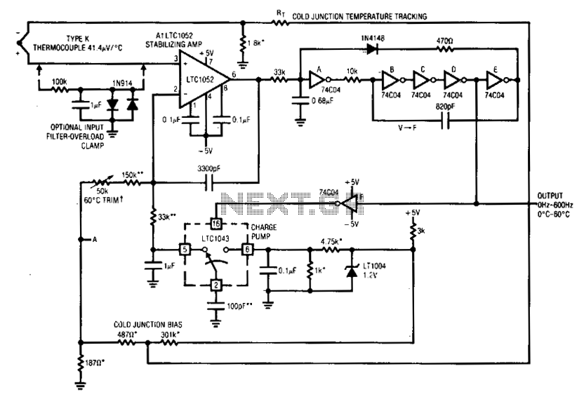
Al's positive input is biased by the thermocouple. Al's output drives a basic voltage-to-frequency (V-F) converter, which consists of 74C04 inverters and related components. Each V-F output pulse results in a fixed amount of charge being transferred from a...
First circuit is for connecting VGA card to video projector or a monitor which accept VGA card frequencies and has RGB + Composite sync input. This circuit has been successfully used with Electrohome Projection Systems ECP 4100 data and...
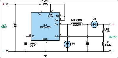
This circuit utilizes mobile phone chargers that incorporate the Motorola MC34063 switch-mode integrated circuit (IC). The output voltage can be adjusted across a broad spectrum by altering the values of the feedback resistors R1 and R2. The output voltage...
The circuit needs that the VGA card sends out the video signal in the RGB format compatible with PAL or NTSC standard video timings. This is accomplished with the right VGA to TV driver. More: This circuit is based...
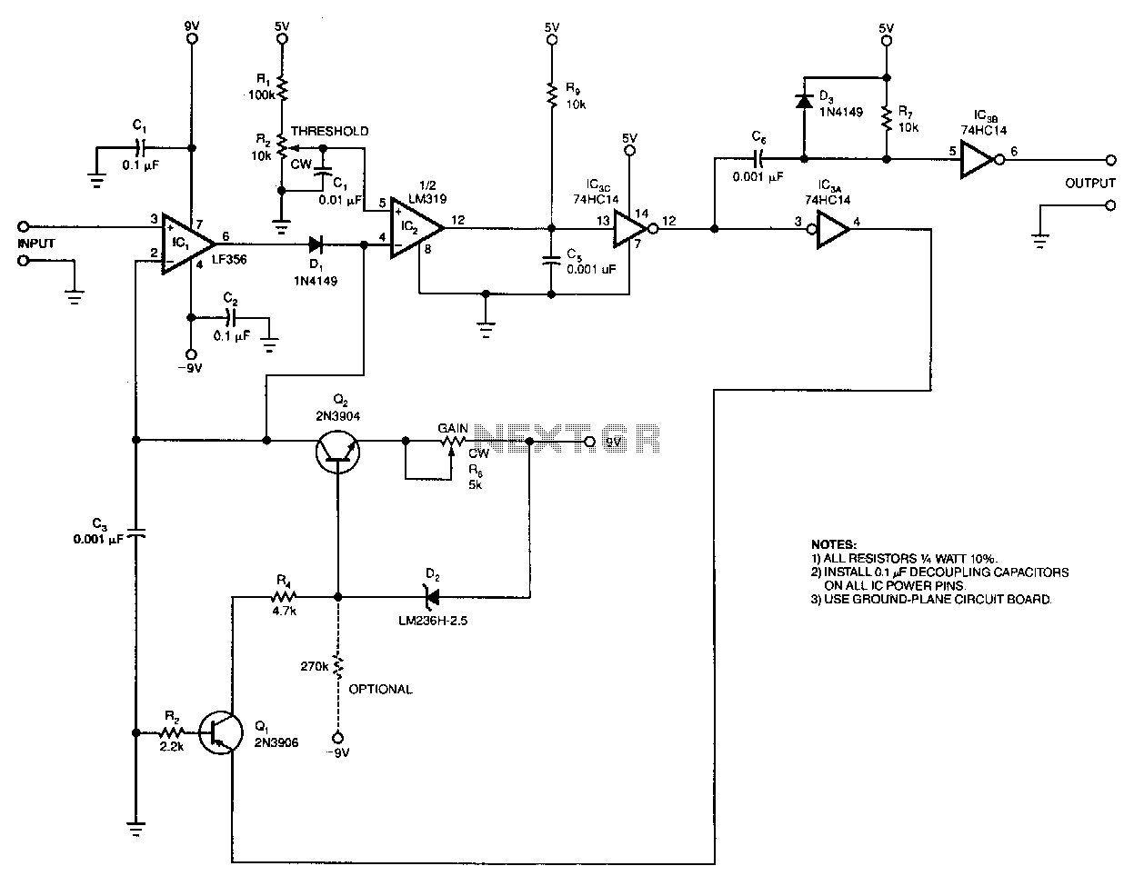
The output pulse width from the circuit is a linear function of the input pulse height. The circuit's input threshold can be set to discriminate against low-level pulses, while fixed components limit the maximum output pulse width. With a...
The lack of compensation facilitates the processes of development and testing. The figure of 6 billion frequently appears as the estimated number of cell phones in use globally. Published estimates indicate an average. The discussion of compensation in electronic circuits...