
vhf dip meter

The dip meter circuit is an essential tool for RF engineers and hobbyists, enabling precise measurements of inductance and frequency within the VHF spectrum. The core components of the circuit include a variable capacitor (C1), a tester coil, and a measurement meter that indicates the resonance dip. The tester coil, typically constructed with two turns of magnet wire, is critical for achieving the desired frequency range, which spans from 50 MHz to 150 MHz.
To utilize the dip meter effectively, the tester coil is inserted into the LX terminals, establishing a connection with the circuit under test. The positioning of the coil is crucial, as it must be placed near the LC circuit to ensure accurate resonance detection. The variable capacitor (C1) allows for fine-tuning of the circuit's resonant frequency. As the capacitor is adjusted, the dip meter displays a decrease in signal strength, indicating that resonance has been achieved.
Calibration of the dip meter is a vital step to ensure accurate readings. This process involves creating a scale based on known LC circuits, which serve as references for the measurements. A frequency counter can expedite this calibration process, providing precise frequency values that can be marked on the scale. This self-constructed scale is essential for interpreting the dip meter's readings correctly.
In summary, the dip meter is a valuable instrument for measuring the resonance of LC circuits in the VHF range. Its design, consisting of a tester coil, variable capacitor, and calibrated scale, allows for accurate determination of frequency and inductance, making it an indispensable tool in the field of electronics.We all know how a dip meter works and what it measures - the resonance of an LC circuit. The circuit featured here is designed to work in the VHF range. The tester coil is inserted in the LX terminals and placed near the LC circuit to be tested. The variable capacitor C1 is slowly turned until a substantial dip is observed in the meter. The freque ncy (or the inductance) can then be read on the scale. The scale must be self constructed by using several LC circuits with known values. The fastest way to calibrate the dip meter (or to make the scale) is to use a frequency counter. The tester coil is 2 turns magnet wire. This gives a frequency range of around 50. 150 MHz. 🔗 External reference
Related Circuits
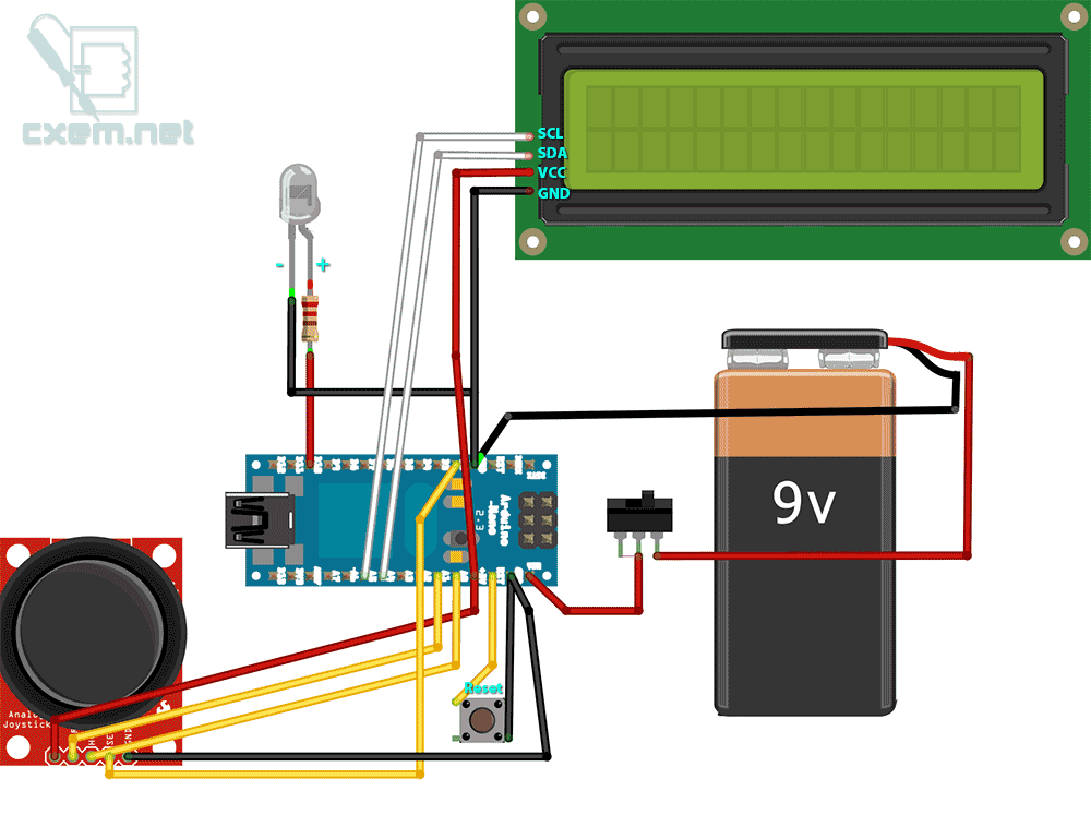
A DIY intervalometer for the Sony NEX 5N camera designed for time-lapse photography. This intervalometer is compatible with most Sony cameras, including the NEX and Alpha series. The circuit utilizes an infrared LED and a Serial LCD with four...

This project involves constructing a simple 3-stage low-power broadcast-type circuit, utilizing a crystal oscillator integrated circuit and a collector modulated AM oscillator with an amplifier. The circuit can be connected to an electret microphone or an amplified dynamic microphone,...
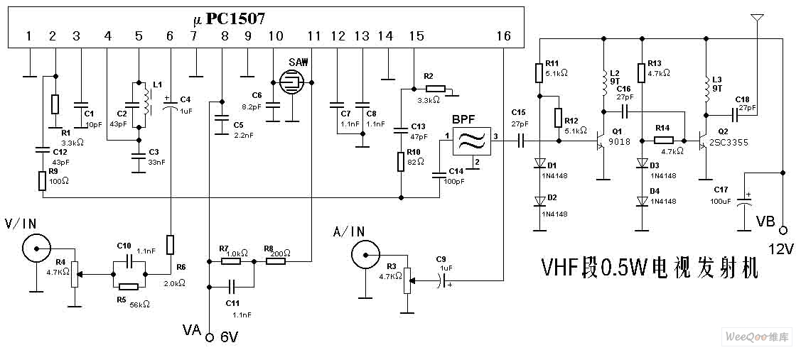
The TV transmitter described here is capable of transmitting audio and video signals from satellite television receivers, VCD players, and video recorders through an open circuit. It can also receive signals using open antennas. This device is ideal for...
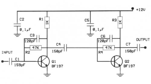
The following circuit illustrates a 20 dB VHF amplifier circuit diagram utilizing the BF197 transistor. Features include a simple circuit design. The 20 dB VHF amplifier circuit is designed to amplify very high frequency signals, making it suitable for applications...
This is a quote attributed to Tesla, taken from his work "On Light and Other High Frequency Phenomena," discussing phenomena produced by various high-frequency effects. The work of Nikola Tesla, particularly in "On Light and Other High Frequency Phenomena," delves...
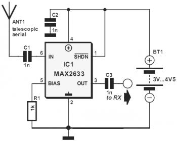
This diagram represents a VHF RF preamplifier circuit operating within the frequency range of 100-175 MHz using a single MAX2633 chip. The circuit is suitable for the entire VHF broadcast and PMR band (100-175 MHz) and can be constructed...