
Video amplifier and video detector

The circuit's design effectively utilizes a high voltage gain of 84 dB, which is critical for applications requiring significant amplification of weak signals. The AGC range of 80 dB indicates a robust capacity to maintain consistent output levels despite variations in input signal strength, thus enhancing the circuit's performance in dynamic environments.
The bandpass shape stability, with less than 1 dB tilt for 60 dB of compression, indicates that the circuit maintains its frequency response characteristics even under substantial signal variations. This quality is essential for ensuring fidelity in audio and communication systems where signal integrity is paramount.
The absence of shielded sections suggests that the circuit is designed for environments where electromagnetic interference (EMI) is not a critical concern, or where the layout minimizes such interference effectively. The use of a single tuned circuit for detection simplifies the design and can enhance reliability, as it reduces the number of components that could potentially introduce noise or failure points.
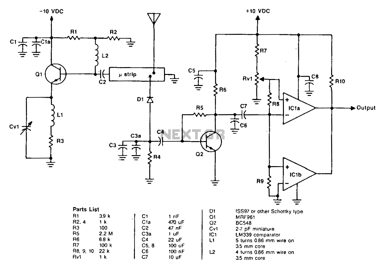
The coupling mechanism between the integrated circuits via a double tuned transformer (composed of L1 and L2) is an efficient method to transfer energy between stages while maintaining impedance matching. This configuration can also help in preserving signal integrity and minimizing losses, which is vital in high-frequency applications. The double tuning allows for improved selectivity and bandwidth control, making the circuit adaptable for various signal processing tasks.
Overall, the design parameters and components used in this circuit suggest it is well-suited for applications in RF amplification and signal processing, where high gain, stability, and efficient coupling are required.The circuit has a typical voltage gain of 84 dB and a typical AGC range of 80 dB. It gives very small changes in bandpass shape, usually less than 1 dB tilt for 60 dB compression. There are no shielded sections. The detector uses a single tuned circuit (L3 and CIO) Coupling between the two integrated circuits is achieved by a double tuned transformer (Ll and L2).
Related Circuits
The circuit on this page is for a simple light detector circuit board that has 8 detectors that can be used with visible or infrared light systems. The detectors use LM339 voltage comparators as the active element. Phototransistors or...
You can use this circuit with any walkman or CD player since it is designed to take a standard 500mv RMS signal. A 15 watt amplifier made using discrete components. Sergio designed this circuit for his Electronics Level II...
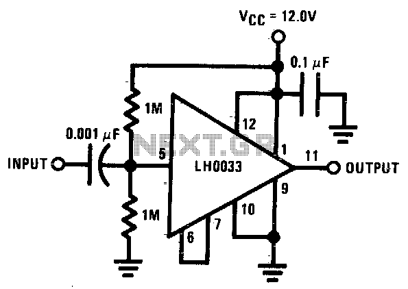
The input is DC biased to the mid-operating point and is AC coupled. Its input impedance is approximately 500K ohms at low frequencies. For DC loads referenced to ground, the quiescent current is increased by the load current set...
The bearing fault detector circuit consists of a bearing detection sensor, a signal processing circuit, a transistor (V), an audio amplifier integrated circuit (IC2), a speaker (BL), an RC element, an integrated circuit (IC1), and a light-emitting diode (VL)....
The oscillator is a standard UHF design that delivers approximately 10 mW at a frequency of 1.2 GHz. Resistors R1 and R2 bias the base of transistor Q1 to 1.2 V through a 12-ohm resistor. The collector current is...

This is a simple and low-cost desktop headphone amplifier designed for office use. The amplifier concept is straightforward and adheres to a typical single-ended Class A circuit. The desktop headphone amplifier utilizes a single-ended Class A design, which is known...