
Bearing fault detector circuit diagram 1

The bearing fault detector circuit is designed to monitor the condition of bearings in machinery, ensuring that any faults are detected early to prevent further damage. The core component of this circuit is the bearing detection sensor, which senses vibrations or anomalies in the bearing's operation. This sensor outputs a signal that is processed by the signal processing circuit, which enhances the signal for better analysis.
The transistor (V) plays a crucial role in amplifying the processed signal to a level suitable for further processing or output. The audio amplifier integrated circuit (IC2) then amplifies this signal to drive the speaker (BL), which produces an audible alert when a fault is detected. The light-emitting diode (VL) serves as a visual indicator, providing a clear signal to operators when an issue arises.
The RC element is used to filter out noise and stabilize the circuit, ensuring that only relevant signals are processed. The integrated circuit (IC1) may include additional processing capabilities, such as signal conditioning or further amplification.
The adjustable resistors, RP1 and RP2, allow for fine-tuning of the circuit's sensitivity and response characteristics. RP1 adjusts the sensitivity of the signal processing circuit, enabling the detection of faults at varying thresholds, while RP2 provides additional adjustment capabilities to optimize performance based on specific operational conditions.
Overall, this bearing fault detector circuit is an essential tool for predictive maintenance in industrial applications, enhancing the reliability and efficiency of machinery by providing timely alerts of potential bearing failures.The bearing fault detector circuit is composed of the bearing detection sensor, signal processing circuit, transistor V, audio amplifier integrated circuit IC2, speaker BL and the RC element, and IC1, light-emitting diode VL, transistor are shown as the chart. RP1 is used to adjust the sensitivity of the signal processing circuit. RP2 is used to adjust the s.. 🔗 External reference
Related Circuits
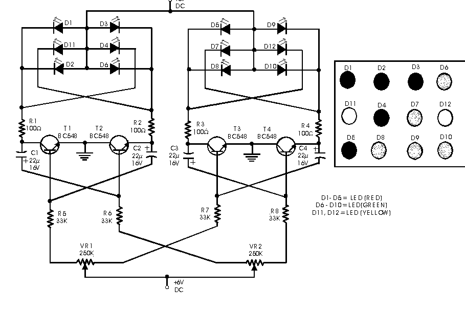
This circuit serves as a decorative element or indicator, featuring adjustable flashing or dancing speeds of LEDs and the ability to create various light patterns. It comprises two astable multivibrators; the first is constructed using transistors T1 and T2,...
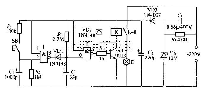
A 2-input NAND gate integrated circuit is used in the fabrication of a digital delay lamp circuit. This circuit is energized by a simple capacitive voltage rectifier, which operates by crossing the half line. The output terminal indicates the...
Design a circuit using a power MOSFET to replace the NTC thermistor that many Mag623 users employ to prevent their bulbs from flashing. Although inexpensive and easy to connect, NTCs run quite hot, are affected by ambient temperature, require...

FIG IC, ICR, Ri, R, and AN composition form a bistable contact circuit with a Ge transistor. It includes components such as ICc, lc, c2, and Dj, and is associated with a one-shot delay circuit. The circuit can be...
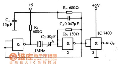
The oscillator circuit consists of a 1MHz quartz crystal resonator and a NAND gate, with the output buffer stage provided by NAND gate 3. This circuit can be utilized for calibrating standard frequency. The described oscillator circuit operates at a...

This is a design of the circuit diagram for an RS422 interface. Connector K1 is connected to the serial port of the PC, and power for the PC side of the circuit is obtained from the signal lines DTR...