
Video amplifier circuit
No description available.
Related Circuits

More: The input data contains a brief description with no additional context or information provided. In the realm of electronics, a circuit schematic typically serves as a visual representation of an electrical circuit. It illustrates the various components such...
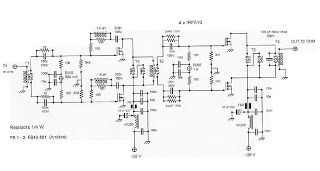
This is an RF Power Amplifier designed for low-cost QRP applications. The circuit operates over a broadband frequency range of 1.8 to 30 MHz, eliminating the need for tuning. The only adjustment required is to set the quiescent current...
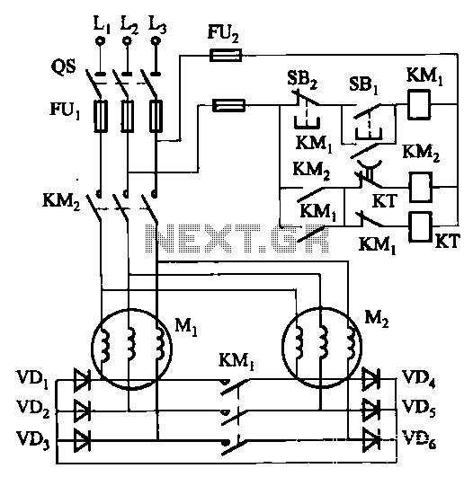
The circuit depicted in Figure 3-157 is designed for motors with a capacity of no more than 11 kW, requiring precise stopping capabilities. Upon shutdown, contact KMi releases, and the motor stator windings are configured into a three-phase rectifier...
A microprocessor cannot drive a motor directly since it cannot supply enough current. Instead, an interface circuit is required so that the motor power is supplied from another source, with only control signals derived from the microprocessor. This interface...
The CXG1024N is a high-power antenna switch MMIC designed to connect a transmitter/receiver (TX/RX) to one of four antennas. This integrated circuit (IC) is fabricated using Sony's GaAs J-FET process and operates with a single positive power supply. The CXG1024N...
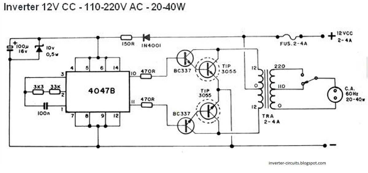
This schematic represents a simple 40W inverter that converts 12V to 220V. It has been functional for four years. The core component of the circuit is a CD4047 integrated circuit (IC) configured as an astable multivibrator. The resistance and...