
video distibution amplifier with five

The described distribution amplifier circuit is designed to enhance the versatility of video signal distribution in various settings, such as auditoriums, classrooms, or home theaters. By utilizing the EL2020 operational amplifier, the circuit ensures high fidelity and minimal distortion in the video signal, allowing for clear and vibrant images on multiple displays. The operational amplifier's bandwidth is crucial for maintaining signal integrity, especially when dealing with composite video signals, which can be sensitive to degradation.
The gain adjustment capability of ±6 dB provides flexibility in managing the output signal level, accommodating different types of video equipment that may have varying input sensitivities. This feature is particularly useful in environments where the distance between the distribution amplifier and the connected devices can lead to signal loss or attenuation.
The choice of the 2N3866 transistor for output buffering is significant, as it is capable of handling the required current and voltage levels while maintaining the integrity of the video signal. The design ensures that each of the five outputs can drive a 75-ohm load, which is the standard impedance for most video equipment, ensuring compatibility and optimal performance.
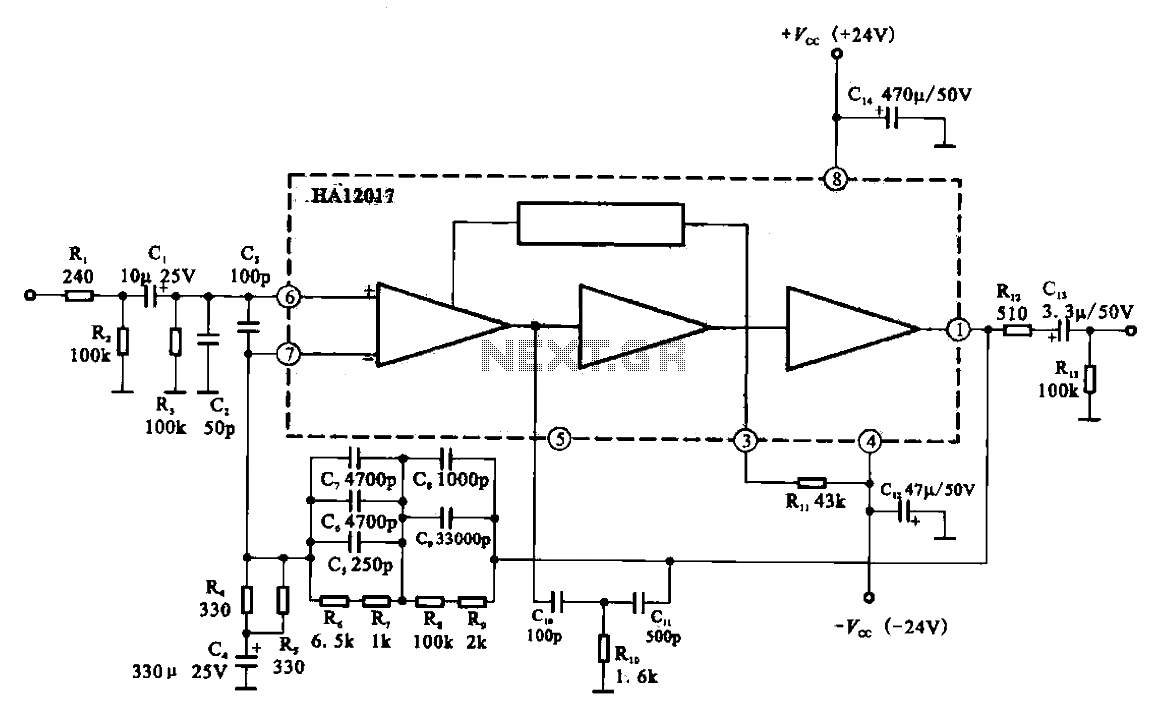
Overall, this circuit serves as an effective solution for distributing composite video signals across multiple devices, enhancing the viewing experience in any application where multiple screens are utilized.The circuit shown here should have a lot of applications. Basically, the distribution amplifier takes the composite video signal from a video player (VCR) or a video generator (analogue output) and buffers it in such a way that it can be simultaneously applied to up to five different video equipment inputs, like monitors, TV sets, other VCRs and so on. For example, in a hall, the image produced by a central DVD player can be shown on five different TV screens with the sound reproduced through a separate amplifier. The circuit is based on the type EL2020 (or similar) operational amplifier which is marled by large bandwidth.
The LL2020 amplifies the video signal applied to the input stage, with a gain adjustment range of ±6 dB. Output transistor Q1, a 2N3866, applies the video signal to the five outputs designed to drive loads with 75- © impedance.
🔗 External reference
Related Circuits
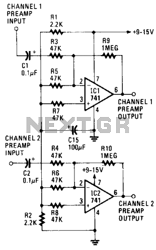
Low-noise preamplifier circuit. This circuit demonstrates a typical low-noise preamplifier design, which can be utilized to amplify signals from sources such as magnetic heads and microphones within audio applications. The input signal is coupled through a capacitor and subsequently...

This car audio amplifier circuit is based on the LA47536 audio amplifier integrated circuit designed by Sanyo. This audio amplifier circuit is specifically designed for car audio power amplifiers. The LA47536 car audio amplifier IC features four output channels...
The gain of the low-cost integrated circuit (IC) is internally fixed at no less than 34 dB (50 times). A unique input stage allows input signals to be referenced to ground. The output is automatically self-centering to one-half the...
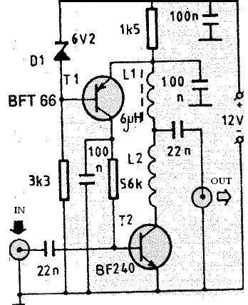
The PCB of this circuit should be positioned close to the antenna within a compact metallic enclosure. This VHF antenna circuit requires a 12 volts DC power supply, which can be sourced from a 12-volt battery, as the current...
The major advantage of amplifiers of this type is that the normal static power dissipation is very low, and the overall power-conversion efficiency is high. Unfortunately, there are also some inherent disadvantages due to the intrinsic dissimilarity in the...
The circuit described is straightforward yet efficient in its operation. The transistor Tr1 is utilized in a grounded base mode, with an input directed to its emitter to facilitate a low impedance input. The circuit is designed to operate effectively...