
Audio preamplifier circuits

If there are plans to operate the circuit from different voltages, it may be necessary to adjust the 1K8 resistor. This adjustment is recommended to ensure symmetrical clipping at high levels, which is crucial for the circuit's performance.
The circuit also allows for the speaker to be used interchangeably as a microphone. To achieve this, the switching should be arranged to short the speaker out before it is disconnected. This arrangement is necessary because the direct current flowing through Tr1 also passes through the speaker. Removing the speaker without shorting it out first could upset the direct current conditions, leading to a large thump in the speaker.
In an alternative scenario, a 1K resistor could be fitted in the emitter, and a 100µF capacitor could be used to couple the speaker. This setup would ensure the smooth operation of the circuit and prevent any potential disturbances that could result from disconnecting the speaker.
In summary, the circuit is simple and efficient, with a well-thought-out design that allows for low impedance input and the possibility of using the speaker as a microphone. It also provides flexibility in terms of operating voltage and ensures smooth operation even at high levels.The circuit is so simple that there is little to say about it, but it gives very good results. Tr1 is operated in grounded base mode with input to its emitter to give low impedance input. The values shown give correct operation from 9v. If operating from other voltages you may wish to alter the 1K8 resistor to give symmetrical clipping at high levels. If you wish to switch the speaker (to use the same speaker as a speaker and as a mic, then you should arrange the switching to short the speaker out before disconnecting it.
This is because the d.c. through Tr1 also flows through the speaker so removing the speaker will upset the d.c. conditions and cause a large thump in the speaker. You could of course fit a 1K resistor in the emitter and use a 100µF capacitor to couple the speaker. 🔗 External reference
Related Circuits
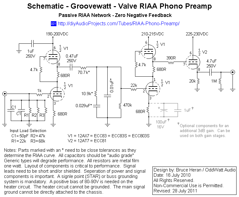
This project has been in development for over a year, initially postponed due to concerns about design complexity and the availability of high-quality phono preamps. The objective was to create a preamp that would deliver performance comparable to commercial...
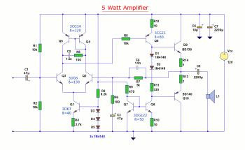
The diagram illustrates a 5W audio amplifier circuit constructed using power transistors BD139 and BD140 for the final amplification stage. This compact amplifier serves as a general-purpose amplifier suitable for applications such as computer audio, radio, MP3 players, and...
This low-cost project enables audio reproduction from a television without disturbing others. It eliminates the need for wired connections between the TV and loudspeakers. Instead, it utilizes invisible infrared light to transmit audio signals from the TV to the...
Nice small audio amplifier which use only few parts to give good quality sound. This amp can be used as a simple booster, the heart of a more complicated amplifier or used as a guitar amp. Although not perfect,...
This circuit diagram represents a microphone preamplifier, specifically designed to prioritize voice signals over other audio inputs. In its basic configuration, the circuit includes a microphone unit and a change-over switch that connects to an amplifier. When the push-to-talk...
This LED (Light Emitting Diode) display consists of 10 LEDs to indicate the level of an input signal. If the signal is low, only LED #1 will light up. As the signal level increases, the illuminated dot will progress...