
Video distribution amplifier

The circuit design incorporates resistors in the output lines primarily to mitigate signal reflections that can occur in unterminated transmission lines. This is crucial in high-frequency applications where impedance mismatches can lead to significant signal integrity issues. The use of resistors aids in damping these reflections, ensuring that the transmitted signal maintains its integrity over distance.
In scenarios where the characteristics of the transmission line are well understood, the output resistors may be omitted, allowing for a more straightforward circuit design without compromising performance. However, careful consideration must be given to the potential for reflections if the line is not properly terminated.
To comply with NTSC (National Television System Committee) gain-phase specifications, a small-value boost resistor is integrated into the circuit. This component is essential for maintaining the required signal levels and phase relationships, which are critical for proper video signal transmission.
The LT1010 operational amplifier is referenced in the context of this design, with Figures 3-27B and 3-27C providing graphical representations of its characteristics. The LT1010 is known for its high-speed performance and low distortion, making it suitable for applications requiring precise signal processing. Understanding its characteristics is vital for optimizing the overall circuit performance, particularly in video signal applications where fidelity is paramount.The resistors in the output lines are included to isolate reflections from unterminated lines. If the line characteristics are known, the resistors can be deleted. To meet NTSC gain-phase requirements, a small-value boost resistor is used. Figures 3-27B and 3-27C show the LT1010 characteristics. 🔗 External reference
Related Circuits
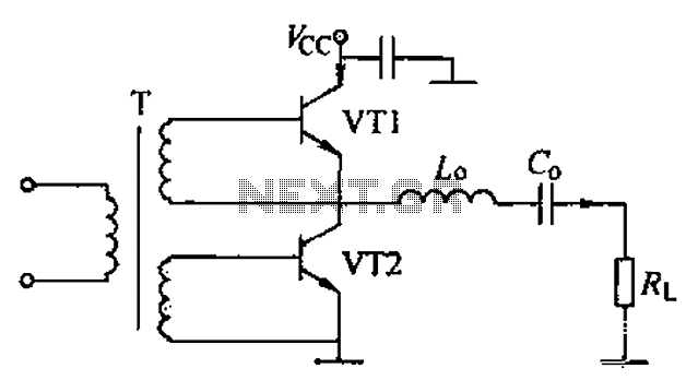
A complementary voltage switching Class D amplifier circuit is presented. Transistors VT1 and VT2 are 3DA12 types, while another transistor, VT3, is of the 3DK41C type. The collector is connected to a constant DC voltage of 12V. The input...
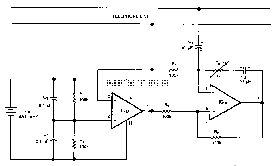
This circuit is a bidirectional amplifier capable of amplifying both signals in a duplex telephone conversation. It operates on the principle of negative resistance. While such an amplifier may be prone to instability, adjusting the load resistor (Rl) can...
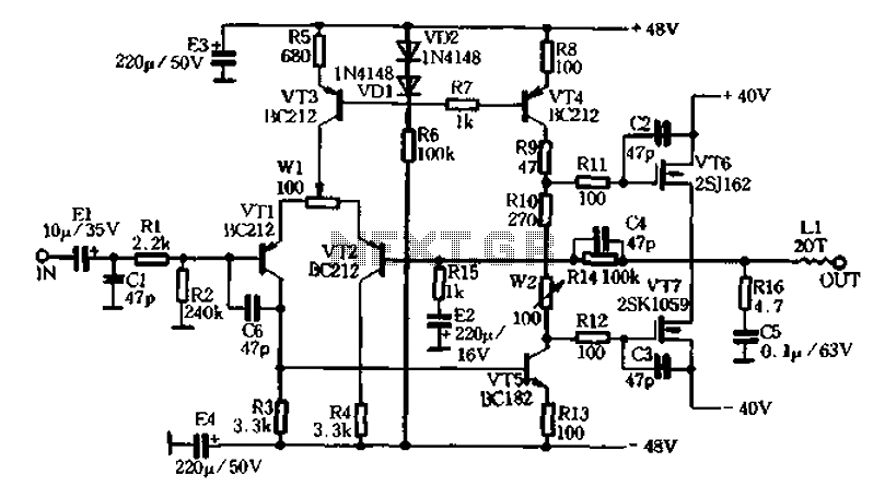
AURA VA50 is a company known for its production starting around 1989, marking a brief history. The launch of its products garnered attention from enthusiasts worldwide, establishing AURA's style. The company manufactured the VA amplifier series, which has been...
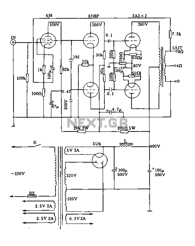
FIG. 2A3A is a low direct thermal resistance transistor with a resistance of only 800 ohms. The output transformer has a primary screen to load impedance of 3.5k ohms. The push-pull amplifier tube operates with a screen voltage ranging...
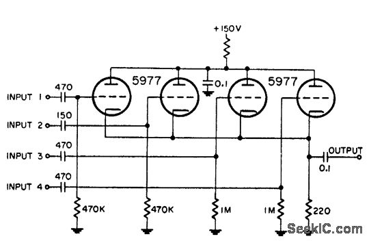
This circuit is utilized for combining four distinct positive-polarity marker pulses in a radar system. The reference for this information is the "Handbook Preferred Circuits Navy Aeronautical Electronic Equipment," Volume 1, Electron Tube Circuits, published in 1963, page N4-1. The...
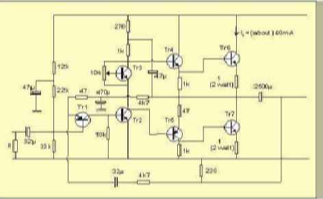
The table below illustrates the expected voltages when utilizing a 24V supply, with the variable resistor adjusted to provide an output current of approximately 40mA. The circuit operates with a 24V DC power supply, where a variable resistor (also known...