
10w audio amplifier

The circuit operates with a 24V DC power supply, where a variable resistor (also known as a potentiometer) is employed to control the current flowing through the output stage. The output stage is designed to deliver a current of about 40mA, which is a critical parameter for ensuring the proper operation of connected components, such as LEDs or other low-power devices.
In this configuration, the variable resistor allows for fine-tuning of the output current by altering the resistance in the circuit. As the resistance is adjusted, the voltage drop across the variable resistor changes, which in turn affects the voltage present at the output. This relationship can be described by Ohm's Law (V = IR), where the voltage (V) across the resistor is equal to the current (I) flowing through it multiplied by the resistance (R).
It is essential to monitor the voltages at various points in the circuit to ensure that they remain within acceptable limits, particularly when the variable resistor is adjusted. The expected voltages can be tabulated based on the resistance settings of the variable resistor, providing a clear reference for users to understand how the adjustments will influence the output current and voltage.
In practical applications, this circuit can be utilized in various electronic devices where precise current control is required, such as in lighting applications, motor speed control, or audio signal processing. Proper design considerations should be taken into account, including the power ratings of the components used and the thermal management of the circuit to prevent overheating during operation.The table below shows the approximate voltages to be expected when using a 24v supply and with the variable resistor set to give a current of about 40mA in the output stage. 🔗 External reference
Related Circuits
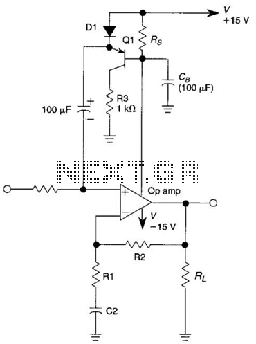
This circuit is an Automatic Gain Control (AGC) system designed for audio-frequency signals. AGC systems typically consist of three main components: an amplifier, a rectifier, and a controlled impedance. In this particular circuit, the functions of both the amplifier...
Here is a little audio amplifier similar to what you might find in a small transistor radio. The input stage is biased so that the supply voltage is divided equally across the two complimentary output transistors which are slightly...
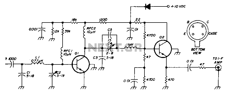
The low-noise preamplifier features a noise figure of 1 dB at 30 MHz and a 3 dB bandwidth of 10 MHz. The gain is 19 dB. The total current drain with a +10 volt supply is 13 mA. The...
The G9 project is an adaptation of the Gyratec IX dual microphone/line/DI preamplifier, tailored to meet the demands of DIY enthusiasts. A thorough search did not yield a complete design for a tube microphone preamplifier, prompting the decision to...
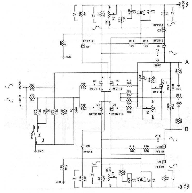
The MOSFETS we are dealing with are three terminal devices which are used to control electron flow in a circuit. Two of the pins (the source and drain) pass the current, and the third pin (the gate) is used...
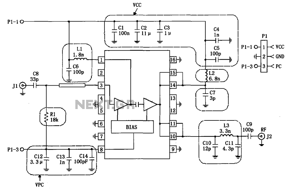
The RF2132 linear power amplifier circuit is depicted in the provided figure. A radio frequency (RF) signal enters through input pin 3 and is processed via a preamplifier. The final stage of the amplifier outputs a gain of 10....