
Video Switcher with PIC16F819

Three numeric sums (modulo 256) are computed from the 64 samples in the video frame. The first sum either adds or subtracts the video sample on a 'checkerboard' basis. Any object moving from one cell to an adjacent one will create a shift in the sum. A second sum is made using a different pattern. This sum is more sensitive to larger objects that may not affect the first sum. Likewise, a third sum is made using yet another pattern. Now we just add the 3 sums. A single 8-bit value now reacts to almost any changes in the visual field. All that needs to be done now is take the samples. There is no way for the PIC's A/D to sample 8 times on a single video scan line. However, it has no trouble taking one sample per line.
U4-A acts as a video clamp; it forces all of the sync tips to zero volts. This allows U4-B to slice off the sync pulses and feed them to the PIC. The PIC can now locate the Vertical Sync by looking for a set of 6 wide Horizontal Sync pulses. It then counts Horizontal Sync pulses to find the start of any particular video line.
The device operates on a motion detection principle that significantly reduces the complexity and memory requirements typically associated with video processing. By sampling only 64 specific locations on the video frame, the design minimizes the data load while still effectively detecting motion. The implementation of three distinct sums, calculated modulo 256, utilizes different sampling patterns to enhance sensitivity to varying object sizes and movements.
The first sum employs a checkerboard pattern, allowing for the detection of minor shifts in the sampled data corresponding to movement between adjacent cells. The second and third sums utilize alternative patterns designed to capture larger objects that may not influence the first sum, ensuring a comprehensive detection capability. The final output of these computations is condensed into a single 8-bit value, which provides a quick reference for any detected changes in the visual field.
The circuit utilizes operational amplifiers U4-A and U4-B to manage video signal processing. U4-A functions as a video clamp, stabilizing the sync tips to a zero-volt reference. This action enables U4-B to effectively extract the sync pulses from the video signal, which are essential for the PIC microcontroller's operation. The PIC then identifies the Vertical Sync signal by detecting a series of six wide Horizontal Sync pulses, allowing it to accurately count and time the Horizontal Sync pulses to determine the beginning of each video line.
This approach not only streamlines the design by reducing component count but also enhances the efficiency of motion detection in multi-camera setups, making it suitable for applications requiring real-time video analysis with minimal processing overhead.This device uses the second method (which, if you don't already know, requires about 100 times less parts), but adds motion detection to switch cameras. The usual way to detect motion is to store a complete video frame and then look for changes on successive frames.
Again, a lot of trouble can be saved by only sampling 64 locations on the screen at a low resolution (i.e. just using the A/D in the PIC). Since this device is designed for up to 4 cameras, that is still a lot of data to store in our PIC. Another method was developed to greatly reduce the memory requirements. Three numeric sums (modulo 256) are computed from the 64 samples in the video frame. The first sum either adds or subtracts the video sample on a 'checkerboard' basis (see fig-1). Any object moving from one cell to an adjacent one will create a shift in the sum. A second sum is made using the pattern in fig-2. This sum is more sensitive to larger objects that may not affect the first sum. Likewise, a third sum is made using the pattern in fig-3. Now we just add the 3 sums! A single 8-bit value now reacts to almost any changes in the visual field. All we need to do now is take the samples. There is no way for the PIC's A/D to sample 8 times on a single video scan line. However, it has no trouble taking one sample per line. U4-A acts as a 'video clamp': it forces all of the sync tips to zero volts. This allows U4-B to 'slice' off the sync pulses and feed them to the PIC. The PIC can now locate the Vertical Sync by looking for a set of 6 wide Horizontal Sync pulses. It then counts Horizontal Sync pulses to find the start of any particular video line. 🔗 External reference
Related Circuits
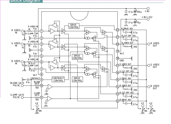
This integrated circuit (IC) is a wideband RGB video amplifier with DC control designed for monitors. It features three matched video amplifiers, a differential input comparator for brightness adjustment, and three matched DC components. The wideband RGB video amplifier is...
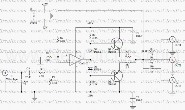
This circuit is useful to amplify and distribute video signals with low noise and without losses. The CA3100 is a fast opamp designed to amplify video signals. Set the P1 to control the input signal level to have a...
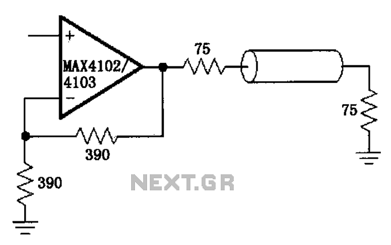
The MAX4102/4103 serves as a video configuration and RF distribution amplifier. The signal input for the MAX4102/4103 undergoes amplification before being output. To minimize the reflection during the transfer process, it is essential to select a termination impedance that...

The circuit is based on the type EL2020 (or similar) operational amplifier which is marked by large bandwidth. The LL2020 amplifies the video signal applied to the input stage, with a gain adjustment range of ±6 dB. Output transistor...
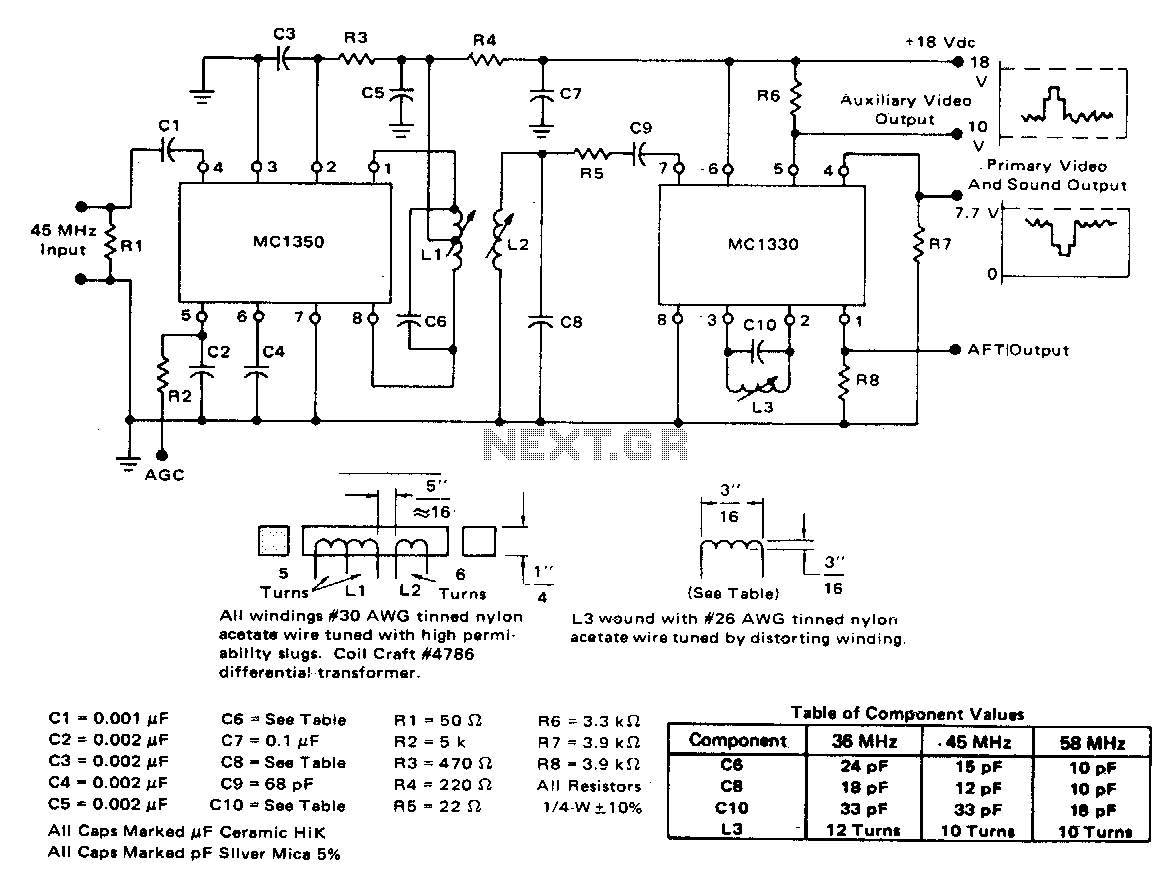
The circuit exhibits a typical voltage gain of 84 dB and an automatic gain control (AGC) range of 80 dB. It demonstrates minimal alterations in bandpass shape, generally less than 1 dB tilt for 60 dB compression. There are...

The LT6552 is a video difference amplifier optimized for low voltage single supply operation. The LT6552 features a 75MHz 3dB bandwidth, a 600V/µs slew rate, and ±70mA output current, making it ideal for driving cables directly. This circuit maps...