
Video title generator

As you can see from the circuit, the PIC does all the work here. The 2N3904 is added to boost the output drive.
Sync pulses are generated in software on RB3. The video character data is sent from the internal SPI port via RB2. This is how so many characters can be generated per line. The SPI port is basically just a hardware shift register - eliminating the usual external shift register used in many video generation schemes.
Incoming data is received via RB0 and generates an interrupt to grab a line of ASCII data. (This causes the display to blank until the complete command is received).
The circuit utilizes a PIC16F819 microcontroller, which serves as the core processing unit. This 8-bit microcontroller is capable of handling various tasks including video generation and data communication. The SPI (Serial Peripheral Interface) port is employed to manage video output, allowing for efficient character rendering on the display. The device is designed to handle a specific character set, primarily uppercase letters and a limited selection of punctuation marks, which are stored in a compact 'folded data table' format to optimize memory usage.
Input data is transmitted to the device through an RS-232 serial connection operating at a baud rate of 9600. This allows for direct communication with a computer's COM port. The data format requires the user to specify a decimal number indicating the desired screen location, followed by the text to be displayed, capped at 20 characters, and concluded with a carriage return. This design enables selective updates to the display without affecting the entire screen, enhancing usability in dynamic applications.
The output stage of the circuit is supported by a 2N3904 NPN transistor, which amplifies the video signal to ensure adequate drive strength for the display. The synchronization pulses necessary for video timing are generated in software using pin RB3 of the PIC16F819. The actual video data, derived from the character set, is sent out through pin RB2 via the SPI port. This method allows for the rapid generation of multiple characters in a single line, leveraging the microcontroller's built-in capabilities to eliminate the need for external shift registers typically used in video applications.
Data reception is facilitated by pin RB0, which is configured to trigger an interrupt when incoming data is detected. This interrupt-driven design is crucial for capturing a complete line of ASCII data, ensuring that the display remains blank until the entire command is processed, thus preventing partial updates that could lead to visual artifacts on the screen. The lines of the display are numbered in increments of 20, from 0 to 140, allowing for flexible positioning of text within the available display area, though care must be taken to avoid automatic line wrapping.Want to add video to your next project? This device uses a PIC16F819 and not much else. Getting 20 characters to a line is possible by using the SPI port to generate video. Neat trick, eh? The character set is limited to upper case and a few punctuation marks and uses a 'folded data table' to store the image data in the space available. Input to the device is via 9600 baud RS-232 directly from a computer com port. Since this device was designed as a status display, data is placed on the screen by sending a decimal number to designate the screen location followed by up to 20 characters of text and a carriage return.
This allows individual portions of the screen to be updated without disturbing the rest of the screen display. Lines are numbered 0,20,40,60,80,100,120, and 140. You can put data starting any place on the screen but do not count on data wrapping to the next line. As you can see from the circuit, the PIC does all the work here. The 2N3904 is added to boost the output drive. Sync pulses are generated in software on RB3. The video character data is sent from the internal SPI port via RB2. This is how so many characters can be generated per line. The SPI port is basically just a hardware shift register - eliminating the usual external shift register used in may video generation schemes.
Incoming data is received via RB0 and generates an interrupt to grab a line of ascii data. (This causes the display to blank until the complete command is received). 🔗 External reference
Related Circuits
This is a 555 tone generator circuit based on the NE555 timer IC. The NE555 is a well-known integrated circuit utilized in various applications and performs a multitude of functions. In this circuit, the IC operates as an astable...
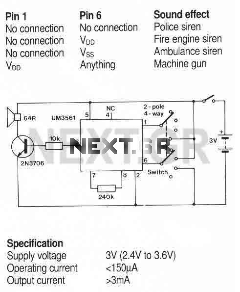
A simple sound generator IC that can produce four sound effects. Designed for use in toys, the effects are selected by varying the connections to pins 1 and 6 as follows. More: A usual toy sounder IC circuit. The sound...
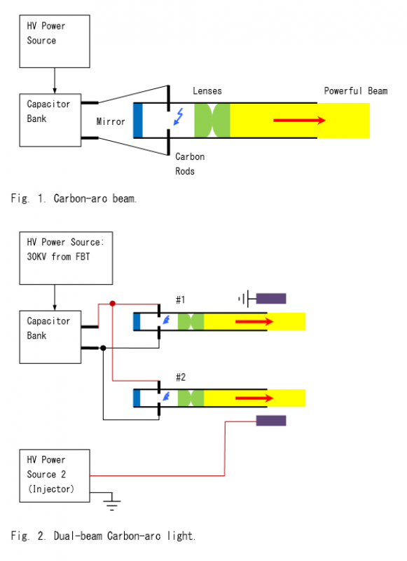
The carbon arc beam was extensively utilized as a searchlight during World War II. A basic configuration is illustrated in Figure 1. The basic beam generator can be modified as shown in Figure 2 to enable high-voltage (HV) electricity...
This circuit generates a two-tone effect similar to the cuckoo song. It can be utilized for doorbells or other applications due to its integrated audio amplifier and loudspeaker. As a sound effect generator, it can connect to external amplifiers,...

The hobby circuit described utilizes a unique approach to generate approximately 12,000 volts with a current of about 5 µA. It employs two silicon-controlled rectifiers (SCRs) that form dual pulse generator circuits. These SCRs discharge a 0.047 µF capacitor...
Here exists a small collection from three generators, which use crystals for the basic production of oscillations. Each generator uses a different topology of circuit for the production of oscillations. The described circuit features three distinct oscillators, each utilizing a...