
Circuit Project: 12KV High Voltage Generator

The circuit operates on the principle of pulse discharge through SCRs, which are semiconductor devices that can control current flow. When triggered, the SCRs allow the discharge of the capacitor through the xenon lamp trigger coil, creating high-voltage pulses. The frequency of 120 Hz indicates that the SCRs are triggered at regular intervals, allowing for consistent pulse generation.
The output from the trigger coil is stepped up in voltage, and the two 6 kV damper diodes rectify the alternating high-voltage pulses into a direct current. The voltage doubler circuit effectively doubles the voltage output, charging the two high-voltage disc capacitors to approximately 12 kV. This configuration is critical for applications requiring high voltage, such as igniting gas discharge lamps or in certain experimental setups.
Safety measures are paramount when working with high-voltage circuits. The design must ensure sufficient spacing between components to prevent arcing and accidental discharge. Proper insulation and the use of components rated for high voltage are also essential to prevent failures and ensure reliable operation. Overall, this circuit exemplifies a creative approach to generating high voltages in a compact and efficient manner, though it requires careful handling and consideration of safety protocols.The hobby circuit below uses an unusual method to generate about 12, 000 volts with about 5uA of current. Two SCRs form two pulse generator circuits. The two SCRs discharge a 0. 047uF a 400v capacitor through a xenon lamp trigger coil at 120 times a second. The high voltage pulses produced at the secondary of the trigger coil are rectified using two 6KV damper diodes. The voltage doubler circuit at the secondary of the trigger coil charges up two high voltage disc capacitors up to about 12KV. Although this circuit can`t produce a lot of current be very careful with it. A 12KV spark can jump about 0. 75 of an inch so the electronic circuit needs to be carefully wired with lots of space between components.
🔗 External reference
Related Circuits
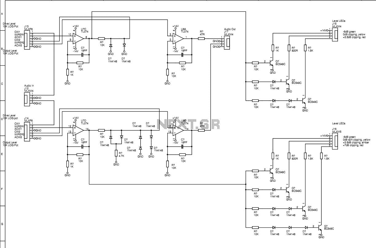
This is a 3U rack unit with standard mains power supply. It provides audio routing and speed control for two domestic three-head cassette tape machines such that they can be used to create authentic 1960s style tape flanging effects....
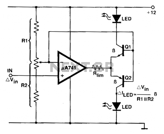
An operational amplifier (op amp) is utilized as a comparator and as a current sink for an LED. The output voltage of the amplifier varies by approximately 1.4 V based on the direction of the current. At any given...
The thermistor utilized has a resistance of 15k ohms at 25 degrees Celsius and 45k ohms at 0 degrees Celsius. A suitable bead-type thermistor can be sourced from the Maplin catalogue. The inclusion of a 100k potentiometer enables this...
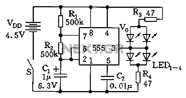
The circuit consists of a 555 timer and a light-emitting diode (LED) array. The 555 timer, along with resistors R1, R2, and capacitor C1, forms an astable multivibrator configuration. The oscillation frequency is calculated using the formula f =...
This schematic represents an FM transmitter capable of delivering an output power of 3 to 3.5 W, operating within a frequency range of 90 to 110 MHz. While the stability of the circuit is acceptable, the integration of a...
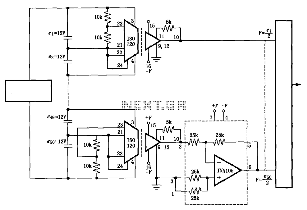
The circuit utilizes the ISO120 and INA105 instrumentation amplifiers to create a battery monitoring system for a 600V battery setup composed of 50 series-connected 12V batteries. This circuit is designed to detect charging and discharging conditions to prevent overcharging...