
Video to RF Signal Conveter

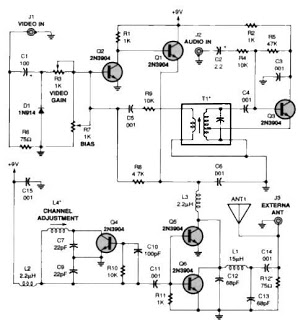
The RF modulator described is designed to convert baseband video signals into radio frequency (RF) signals suitable for transmission over the VHF band. The modulation process typically involves amplitude modulation (AM) or frequency modulation (FM) techniques, which allow the video information to be encoded onto a carrier wave.
Key components of the RF modulator circuit may include:
1. **Video Signal Input**: The circuit accepts composite video signals, which can be sourced from devices such as cameras or video playback equipment. This input is processed to extract the luminance (brightness) and chrominance (color) information.
2. **Control Potentiometers (P1 and P2)**:
- P1 is responsible for adjusting the brightness level of the video signal. By altering the gain of the video signal, the user can increase or decrease the light intensity in the output image.
- P2 adjusts the contrast of the video signal. This control modifies the difference between the lightest and darkest parts of the image, enhancing the overall visual quality.
3. **Modulation Circuit**: This section of the circuit modulates the video signal onto a carrier frequency, which is set to approximately 189 MHz for VHF transmission. It may consist of an oscillator to generate the carrier frequency and a modulator that combines the video signal with the carrier.
4. **Output Stage**: The modulated RF signal is then amplified to ensure sufficient power for transmission. This stage may include RF amplifiers that boost the signal strength before it is sent to an antenna for broadcasting.
5. **Antenna**: The antenna is designed to radiate the modulated RF signal into the air, allowing it to be received by compatible VHF receivers.
It is important to note that this RF modulator is specifically designed for video signals and does not include provisions for audio modulation. As a result, any audio component associated with the video source must be transmitted separately or handled by a different audio transmission system. This design focus allows for a simplified circuit that prioritizes video quality and modulation efficiency.This circuit is a RF modulator which can be used for modulating of video signals. The P1 controls the Light and the P2 controls the contrast of video signal. The RF modulated output signal can be received on the VHF band ( about 189 MHz ). Note that the circuit don't modulate the audio signal of the pictures. 🔗 External reference
Related Circuits
This article provides a brief overview of the NTSC-PAL TV Signal Identifier, specifically utilizing the LM1881. The circuit is straightforward to understand and highly practical. A deep comprehension of the circuit elements and their principles is essential for effective...
An NE592 or LM733 is utilized as a general-purpose video amplifier in this schematic. J2 and J3 deliver two anti-phase outputs. R2 functions as a gain control. The bandwidth is approximately 100 MHz. The NE592 and LM733 are operational amplifiers...
A simple TV audio-video transmitter circuit can be constructed using this schematic diagram. This circuit allows for the transmission of video signals from a VCR or other devices to a TV without the need for cables. The video signals...
The circuit described is a simple audio/video transmitter with a range of 3 to 5 meters. The A/V signal source can be a VCR, satellite receiver, or video game console. A mixer that functions as an oscillator at the...
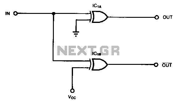
Some applications, such as driving three-state buffers for data multiplexers or for biphase clocks in high-speed systems, require complementary signals with minimal time skew and nearly simultaneous transitions. In this context, XOR gates serve as both inverting and non-inverting...
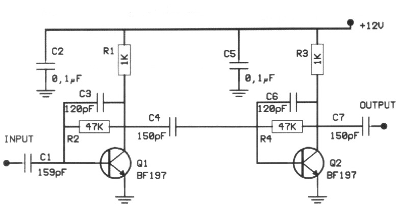
Many times we needed to strengthen a small signal in the region of VHF or FM. The preamplifier that we propose offers 20dB in all the region of VHF and it still can reach also their 500MHz. The amplifier...