
Enlarging Light Meter Circuit

A variable positive current, determined by the settings of R14 and S1, is derived from the positive supply rail and also fed to pin 3 of Ul. When the two currents, which have opposite polarities, are equal, they cancel each other out, resulting in no current applied to pin 3 of Ul. Consequently, the output of Ul becomes zero, and meter Ml registers accordingly, indicating a null. However, when light strikes R16 and its resistance decreases, the current through the device increases, making the negative current greater than the positive current. This causes the output of Ul to swing negative, leading the pointer to move in the negative direction, indicating that the light intensity must be reduced by using a smaller lens opening on the enlarger (smaller f-stop). Conversely, if the light is too dim, the opposite occurs. Lamp L1, a 12-V 60-mA grain of wheat unit, illuminates the meter scale, while R15 limits the meter's illumination to a faint glow, ensuring the face of Ml is visible in a photo darkroom. Resistors R3 and R4 should be selected based on the meter used. With a dual supply of +/-12 V, Ul produces an output voltage of 10 V peak-to-peak. The resistance of R3 can be calculated by dividing the peak voltage (10/2) by the full-scale meter current (in amps); thus, R3 = (10/2)/0.0005 = 100,000 ohms. R4, the shunt resistor, should be selected to match the meter's internal resistance.
The described circuit utilizes a TL081 FET operational amplifier, which is ideal for low-noise applications due to its high input impedance and low bias current. The configuration allows for precise control over the gain and bandwidth, ensuring accurate readings from the D'Arsonval meter. The LDR's integration into the circuit enables real-time light intensity measurement, which is critical in applications such as photographic darkrooms where light levels must be carefully controlled.
The dual-polarity power supply design is essential for providing the necessary voltage levels to the op-amp and ensuring that the meter can accurately reflect both positive and negative deviations from the null point. The selection of resistors R3 and R4 is crucial for calibration, as R3 must be calculated based on the specific characteristics of the meter movement to ensure that it operates within its specified current range. R4's value should match the meter's internal resistance to prevent loading effects that could distort the readings.
The use of a variable positive current through R14 and S1 allows for dynamic adjustments based on the light conditions, providing flexibility in operation. The system's feedback mechanism, which relies on the balance of currents at pin 3 of Ul, forms the core of its functionality, enabling it to indicate whether adjustments to the light intensity are necessary. This feedback loop, combined with the visual indicator provided by the illuminated meter scale, ensures that users can make informed decisions regarding exposure settings in photographic processes. Meter Ml, a +/-50-uA zero-center D`Arsonval meter movement is driven by Ul, a TL081 FET op amp, through R3. The gain of Ul is set at 11 by Rl and R2, while capacitor 01 is used to restrict the bandwidth of Ul to 1.6 Hz.
Power for the circuit is derived from a simple dual-polarity 12- V power supply (consisting of Tl, D3, D4, 02, and 03). A light-dependent resistor (LDR), R16 (which is a semiconductor element whose resistance decreases as it is exposed to increasing illumination), is used as a light-sensing device.
One end of R16 is connected to the negative supply rail through R12, arid the other end is connected to pin 3 of Ul, applying a negative current to Ul. A variable (over a 4:1 range) positive current determined by the settings of R14 and Si (and derived from the positive supply rail) is also fed to pin 3 of Ul. When the two currents (of opposite polarities) are equal, they cancel each other out, so effectively no current is applied to pin 3 of Ul.
With no current applied to pin 3, the output of Ul is zero and meter Ml registers accordingly, indicating a null. However, when light striking R16 causes its resistance to decrease, the current through the device increases, making the negative current greater than the positive current.
Under that condition, the negative current causes the output of Ul to swing negative, causing the pointer to swing in the negative direction. That indicates that the light intensity must be reduced by using a smaller lens opening on the en-larger (smaller f/stop).
The opposite occurs if the light is too dim. Lamp 11, a 12-V 60-mA grain of wheat unit, is used to illuminate the meter scale, and R15 is used to limit the meter`s illumination to a faint glow that is just blight enough so that the face of Ml can be plainly seen in a photo darkroom. Resistors R3 and R4 should be selected for the meter used. With a dual supply of +/-12 V, Ul produces an output voltage of 10 V peak-to-peak. The resistance of R3 can be found by dividing the peak voltage (i.e., 10/2) by the full-scale meter current (in amps); i.e., R:] = (10/2)/0.0005 = 100,000 .
R4, the shunt resistor, should be selected to have a value equal to Hie meter`s internal resistance.
Related Circuits
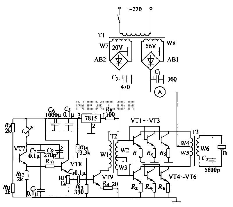
The ultrasonic drilling machine is essential machinery in the dairy industry for processing jewelry, primarily for natural stones, crystal agate, jade, and glass products. This machine is particularly effective for high-hardness materials, enabling both drilling and engraving. The following...
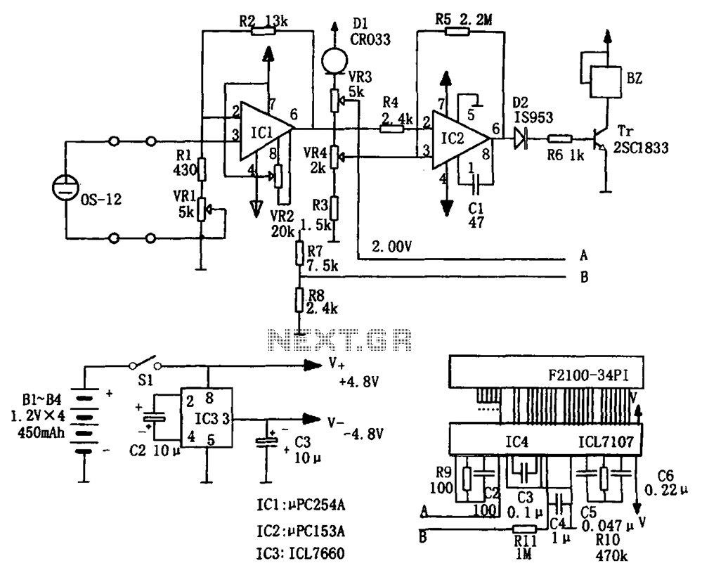
The portable hypoxia monitoring circuit comprises the oxygen sensor OS-12, a DC amplifier IC1, an A/D converter IC4, and a liquid crystal display F2100-34PI. Additionally, it includes a voltage comparator IC2 and a positive and negative power converter IC,...
Schematic and description of a simple automatic NiMH battery charger circuit using IC 7805 with multiple selectable current options for charging. The described circuit is a straightforward automatic charger designed for Nickel-Metal Hydride (NiMH) batteries. It utilizes the IC 7805...
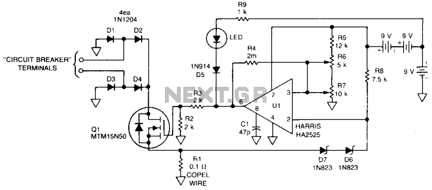
This 115 Vac electronic circuit breaker utilizes the low drive power, low on-resistance, and fast turn-off characteristics of the TMOS MTM15N50. The trip point is adjustable, and an LED fault indication is provided, with battery power ensuring complete circuit...
The motion sensor switch circuit is a motion sensor-controlled automatic water sprinkler, but an alarm or light function can be easily added as well. The motion sensor switch circuit utilizes a passive infrared (PIR) sensor to detect motion within...
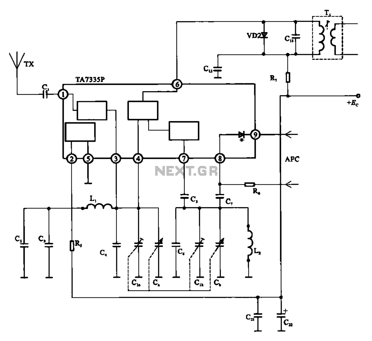
The FM front-end circuit, also referred to as an FM receiver circuit, is composed of discrete components. This configuration presents challenges in debugging and is prone to difficulties in miniaturization, leading to its gradual replacement by FM radio integrated...