
automatic nimh battery charger circuit

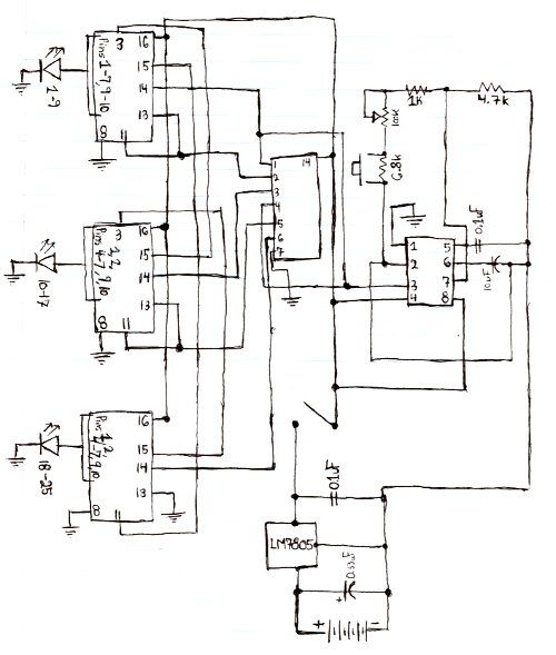
The described circuit is a straightforward automatic charger designed for Nickel-Metal Hydride (NiMH) batteries. It utilizes the IC 7805 voltage regulator, which is commonly employed to provide a stable output voltage of 5V. This circuit is particularly advantageous due to its ability to offer multiple selectable current options for charging, allowing users to adjust the charging rate according to the specific requirements of the battery being charged.
The schematic typically includes the IC 7805, which serves as the main voltage regulator, ensuring that the output voltage remains consistent regardless of variations in the input voltage or load conditions. Additionally, various resistors and switches are integrated into the circuit to facilitate the selection of different charging currents. By altering the resistance value, the charging current can be modified, thus accommodating batteries of different capacities and charge states.
Furthermore, the circuit may incorporate additional components such as diodes to prevent reverse polarity and protect the circuit from potential damage. Capacitors may also be included to filter out voltage spikes and stabilize the output. An LED indicator can be integrated to provide visual feedback on the charging status, signaling when the battery is charging or fully charged.
This automatic charger design is suitable for hobbyists and professionals who require a reliable and adjustable solution for charging NiMH batteries, ensuring safe and efficient battery management.Schematic and description of simple automatic NiMH battery charger circuit using IC 7805 with multiple selectable current options for charging. .. 🔗 External reference
Related Circuits
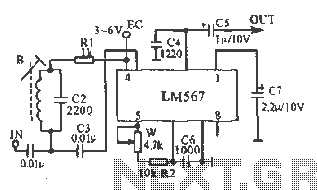
This figure illustrates the schematic of the LM567 SCA broadcast reception information machine. The LM567 serves as a narrow-band phase-locked loop designed primarily for SCA broadcast demodulation. The configuration includes a potentiometer (W) and capacitor (C6) that determine the...
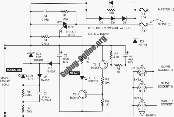
This circuit design features a modular arrangement that enables users to select only the modules best suited to their needs, allowing for the construction of a chain ranging from one to five modules in length. For those seeking a...
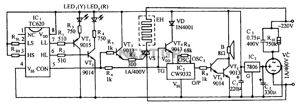
The circuit includes the TC620 temperature control circuit, the temperature indicator circuit, a thyristor-controlled heating circuit, a vocal music buck rectifier circuit, and the AC circuit. The TC620 temperature control circuit is designed to regulate temperature by monitoring the temperature...
Here is the schematic for the circuit. Solder all the components onto a perfboard. The drawings may not be very clear. Essentially, the 555 timer generates a pulse. The circuit utilizes a 555 timer IC configured in astable mode, which...
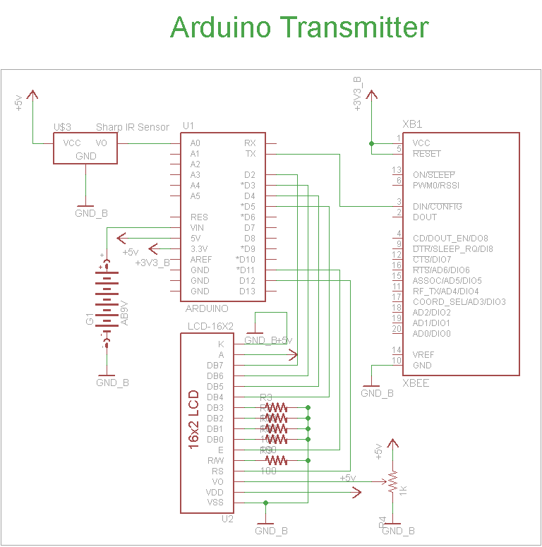
The schematic for the transmitter in this project consists of four main components: the Arduino UNO, the Sharp IR distance sensor, the XBee wireless modules, and a 16x2 LCD. The connections between these components are illustrated in the schematic....
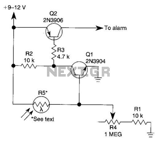
The circuit functions as a sensor capable of triggering an alarm without direct contact from an intruder. It utilizes a visible or invisible light source that illuminates the sensor, maintaining the detection loop in a normally closed state. As...