
PAL colour bar generator

To design a circuit that utilizes an 8.867238 MHz crystal oscillator for generating a PAL video composite signal, the primary component is the crystal oscillator itself, which serves as the frequency reference. The crystal frequency is chosen to be double the color carrier frequency of 4.43 MHz. This frequency will be divided down to generate the necessary signals for color encoding.
The circuit can be structured using a phase-locked loop (PLL) that locks onto the 8.867238 MHz signal and generates the required 4.43 MHz color carrier signal. The PLL will include a voltage-controlled oscillator (VCO), a phase comparator, and a loop filter. The VCO will be configured to output the 4.43 MHz frequency, while the phase comparator will ensure that the output remains in phase with the reference signal from the crystal oscillator.
To achieve the four-color output, the circuit will implement a digital logic section that modifies the phase of the color carrier signal. This can be accomplished using a series of flip-flops or a microcontroller programmed to output the desired phase shifts. The phase shifts correspond to the different colors in the PAL format: for instance, the phase shift can be set to 0 degrees for one color, 90 degrees for the second color, 180 degrees for the third color, and 270 degrees for the fourth color.
The color burst signal, which is essential for synchronizing the color information in the video signal, must be adjusted from its standard phase of 135 degrees to 225 degrees. This can be achieved by adding a phase shifter circuit, which can be implemented using an analog phase shifter or by further manipulating the digital signal using a microcontroller.
In summary, the circuit design will encompass a crystal oscillator, a PLL for frequency generation, a digital logic section for phase manipulation, and a phase shifter for the color burst signal. This comprehensive approach will allow for the effective generation of a PAL video composite signal with accurate color representation.The first idea they was to work with 8.867238 MHz crystal (2 times the color carrier). When I read more about PAL video composite signal creation, I saw that, if you want to product colors entire-in-software you must to create the color-carrier (4.43 MHz), to change 4 times the phase of color-carrier (one time for each color), to show 4 colours. Except that, you have to change the color-burst from 135 deg to 135+90= 225 deg. 🔗 External reference
Related Circuits
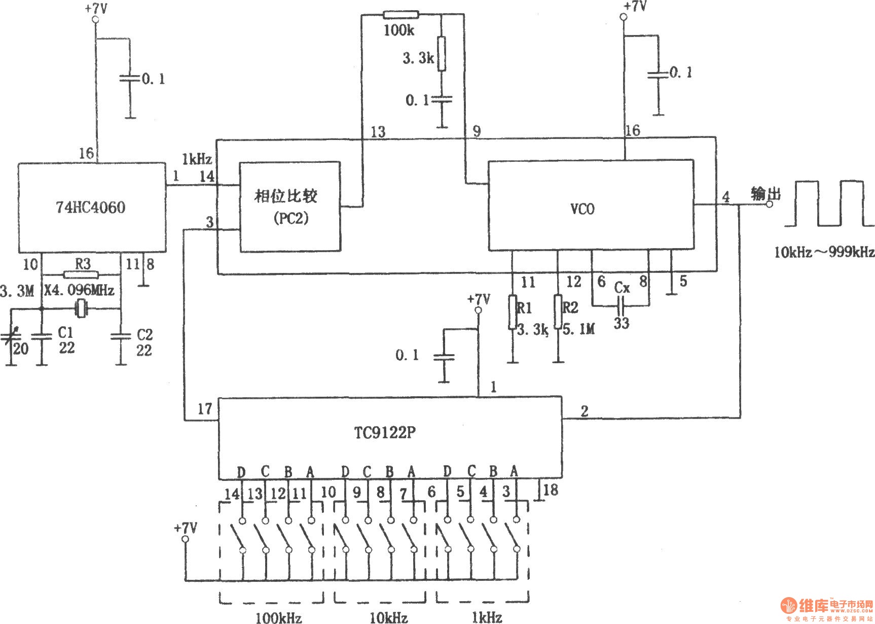
The PLL pulse generator is illustrated in the accompanying chart. The circuit represents a phase-locked loop (PLL) pulse generator. The PLL generates a fractional frequency from a crystal oscillator, producing a 1 kHz stepped frequency signal. Additionally, it outputs...
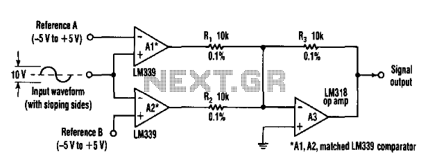
This circuit can extract harmonics from various waveforms. With a sloped input waveform, the comparator produces a pulse width that is proportional to a reference plus input amplitude. As the pulse width changes, the harmonics spectrum changes. Combining the...
This is a simple function generator built around a single 8038 waveform generator IC. The circuit is capable of producing sine, square, or triangle waves within a frequency range of 20Hz to 200kHz. The function generator circuit utilizes the 8038...
The function generator features two BNC outputs: one for the high speed [1 to 8 MHz] square signal (BNC1) and another for the DDS signal (BNC2). Offset and amplitude can be regulated by two potentiometers: offset in range of...
The circuit employs a widely used Sharp IR module (the Vishay module may also be utilized). The pin numbers indicated in the circuit pertain to both the Sharp and Vishay modules. For other modules, it is recommended to consult...
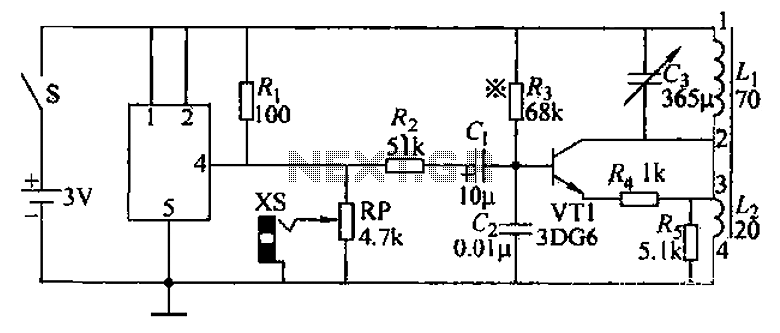
An audio frequency signal generator can output audio signals, 465 kHz spectral amplitude signals, and 52.5 Hz to 16 kHz high-frequency amplitude-modulated signals. The high-frequency oscillator's vibration frequency is determined by the components G and L. A variety of...