
Audio-frequency generator circuit

The audio frequency signal generator described operates within a specified frequency range, generating audio signals and modulated high-frequency signals. The circuit employs a high-frequency oscillator, which utilizes inductive (L) and capacitive (G) components to establish the desired oscillation frequency. The pilot signal from receptacle XS serves as a reference for generating various musical tones. The modulation of the high-frequency signal is accomplished through the interaction of resistor R and capacitor C1, which shape the output into amplitude-modulated waves.
The variable resistor RP plays a crucial role in controlling the output signal's amplitude, allowing for adjustments based on the application requirements. The magnetic antenna is designed with two windings, W1 and W2, which are critical for efficient signal transmission. W1, with 70 turns, and W2, with 20 turns, provide the necessary inductance for effective radiation of the high-frequency signal.
The tuning capacitor G is integral to the circuit's functionality, as it enables fine-tuning of the oscillation frequency. By adjusting capacitor C3, the operating frequency can be extended from 460 kHz to 1610 kHz, facilitating a wide range of applications. The design allows for flexibility in the number of turns in winding W1, accommodating different frequency requirements.
The bias resistor Yan is essential for stabilizing the transistor VT1, ensuring consistent performance. By maintaining the collector current within the specified range of 0.8 mA to 1.2 mA, the circuit achieves optimal operation and reliability. This comprehensive design allows for effective generation and modulation of audio and high-frequency signals, suitable for various electronic applications.An audio frequency signal generator shown in FIG. Can output audio signal, 465kHz spectral amplitude signals, 52,5Hz4-16Q5kHz high frequency amplitude modulated signal. VT1 hig h-frequency oscillator and the like, the vibration frequency of oscillation by the G, L. Decision. Manifold musical tone generated by the pilot signal on the one hand from the receptacle XS output, on the other hand by the R, c1 to modulate the high frequency signal to produce AM waves. Potential RP is used to adjust the size of the audio output signal., The high -frequency signal from the magnetic antenna direct radiation output by changing to adjust the distance and the relative position signal generator and a receiver the size of the output signal.
Magnetic antenna in the magnet forward Wl wound 70 turns, W2 around 20 turns. G is a tuning capacitor, change C3 should be able to cover 460kHz-1610kHz, or can increase or decrease the number of turns Wl achieved. Yan is the bias resistor, adjust Ningbo, make VT1 collector current of 0.8 ~ 1. 2mA can.
Related Circuits
If you are expecting an important visitor but need to step out for a moment, an electronic doorbell memory can be useful to check whether someone rang while you were away. While it cannot confirm if it was the...
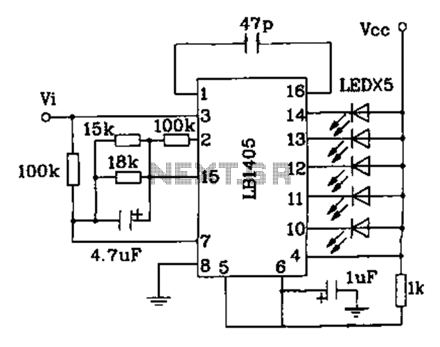
The LB140 is depicted in Figure as a typical driver IC circuit for a five-digit LED level indicator. The BL1405 is commonly utilized in tape recorders for level indication. The LB140 integrated circuit serves as a driver for five-digit LED...
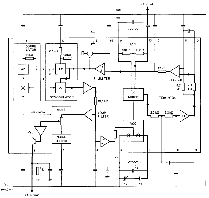
GENERAL DESCRIPTION The TDA7000 is a monolithic integrated circuit designed for mono FM portable radios or receivers, emphasizing minimal peripheral components to achieve compact dimensions and reduced costs. This integrated circuit features a Frequency-Locked-Loop (FLL) system with an intermediate...
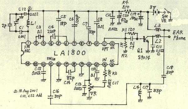
Earphones, batteries are sold separately. AM / FM seems to be a common mold. But stamping is different. AM / FM E193577 UL94V0 board with the AM / FM etching printed circuit board manufacturers are the same. Shape is...
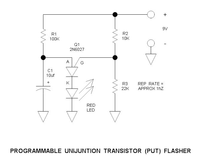
This is a simple circuit that illustrates the function of the programmable unijunction transistor. It can be quickly wired on a proto-board. The circuit utilizes a programmable unijunction transistor (PUT) to demonstrate its operation as an oscillator. The PUT, which...
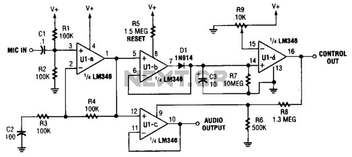
In specific applications, such as transmitters or other communications and control systems, this circuit is designed to be beneficial. It provides both audio output and DC control outputs. Additionally, R9 establishes the control threshold. The circuit in question is versatile...