
Vlf Converter Circuit

The frequency converter is designed to enable the reception of signals in the VLF range, typically used for various communication and navigation applications. The circuit employs a frequency mixing technique, where the input signal within the 10 kHz to 150 kHz range is combined with a local oscillator signal at 4 MHz. This mixing process generates new frequencies, specifically the desired output range of 4.01 to 4.15 MHz.
The circuit includes the following key components:
1. **Antenna**: A long antenna is essential for optimal reception of VLF signals. The length of the antenna should ideally be a quarter wavelength of the lowest frequency of interest to enhance sensitivity and reduce noise.
2. **Crystal Oscillator (XI)**: The crystal oscillator serves as the local oscillator for the mixer circuit. It generates a stable 4 MHz signal that is crucial for accurate frequency conversion. The choice of crystal can influence the stability and performance of the converter, and therefore, selecting a microprocessor crystal or another suitable type is recommended.
3. **Mixer Circuit**: The core of the converter is the mixer, which combines the input VLF signal with the 4 MHz oscillator signal. This component can be implemented using various technologies, including diode mixers or integrated circuit mixers, depending on the desired performance characteristics and complexity of the design.
4. **Output Filtering**: After mixing, the output signal may contain unwanted frequencies (harmonics and sidebands). A band-pass filter is typically employed to isolate the desired frequency range of 4.01 to 4.15 MHz, ensuring that only the relevant signals are passed to the shortwave receiver.
5. **Amplification**: To enhance the signal strength before it reaches the receiver, an amplifier stage may be included. This stage is crucial for maintaining signal integrity and improving the overall sensitivity of the receiver system.
The overall design should prioritize minimizing noise and distortion to ensure clear signal reception. Proper PCB layout techniques and grounding practices should be employed to avoid interference from other electronic components. This frequency converter is a versatile tool for expanding the capabilities of shortwave receivers, enabling them to capture a broader range of frequencies effectively. This converter converts 10 kHz to 150 kHz to 4.01 to 4.15 MHz 1`or use with a shortwave receiver for VLF reception. A 4-MHz L.. frequency is used. XI can be a microprocessor XTAL or another suitable type. The antenna should be as long as possible.
Related Circuits
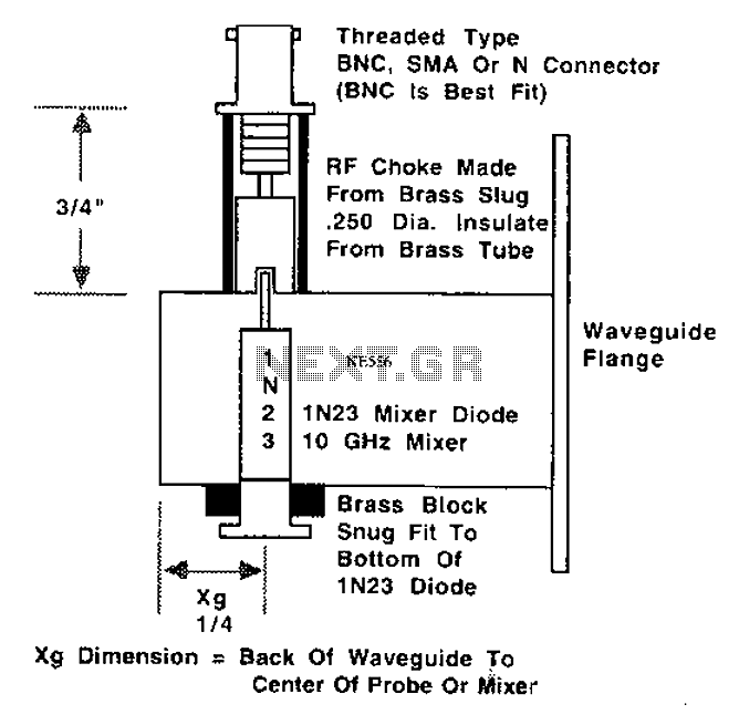
This is a 10 GHz frequency amateur radio waveguide detector. The 10 GHz amateur radio waveguide detector is designed to operate within the microwave frequency range, specifically targeting the 10 GHz band commonly used in various amateur radio applications. The...
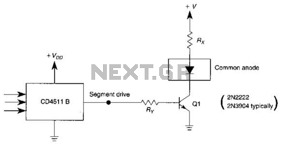
The use of a switching transistor, such as a 2N2222 or 2N3904, enables the operation of the CD4511B with a common-anode display. The transistor should be selected to provide approximately 1 mA to drive Q1, while resistor Rr must...
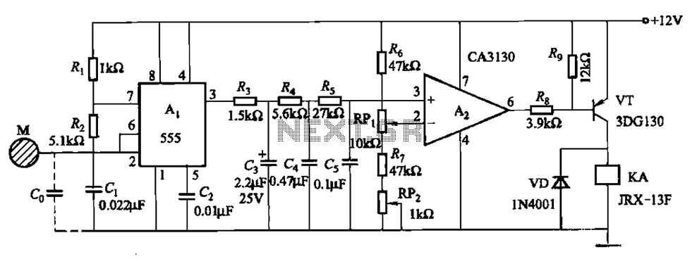
The circuit utilizes a 555 IC in conjunction with capacitors C1, C2, and a metal plate (tablet) M to create a distributed capacitance Co and resistor R1 connected to ground. Resistor R2 forms a self-excited multivibrator, while resistors R3...
The circuit is a battery charging system powered by Q2, Q6, R8, and D10, which provides constant current to charge the battery. When an external power supply is present, the charging current flows through R8 and D10 to charge...
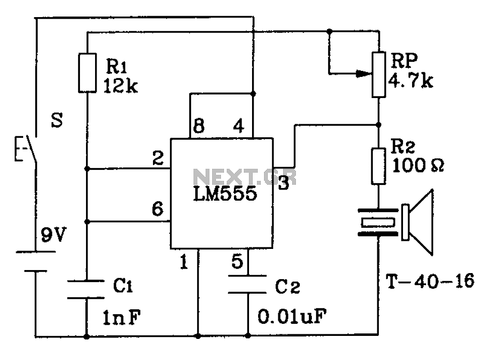
The circuit described is a 555 ultrasonic transmitter constructed to emit ultrasonic signals at a frequency of 40 kHz. It operates by generating oscillating pulse outputs from a 555 timer (specifically the T-40-16 model). The circuit is designed to...
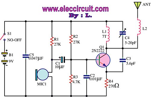
This is an FM wireless transmitter circuit designed to operate a microphone without the need for a cable connecting the microphone to the amplifier. The FM wireless transmitter circuit typically consists of several key components: a microphone, an oscillator, a...