
FM wireless transmitter circuit

The FM wireless transmitter circuit typically consists of several key components: a microphone, an oscillator, a modulator, and an antenna. The microphone captures sound waves and converts them into electrical signals. These electrical signals are then fed into the oscillator, which generates a carrier frequency. The modulator combines the audio signal from the microphone with the carrier frequency produced by the oscillator, effectively encoding the audio information onto the carrier wave.
The output of the modulator is then transmitted through an antenna, which radiates the modulated signal as electromagnetic waves. The design of the antenna is crucial for ensuring efficient transmission and reception of the signal. The circuit may also include additional elements such as filters to remove unwanted frequencies, amplifiers to boost the signal strength, and power supply components to ensure stable operation.
In practical applications, the FM wireless transmitter circuit is widely used in various audio transmission scenarios, including public speaking, musical performances, and broadcasting. The absence of a physical connection between the microphone and the amplifier provides greater freedom of movement for the user while maintaining high audio quality. Proper tuning of the circuit is essential to achieve optimal performance, with considerations for frequency stability, range, and audio fidelity.This the fm wireless transmitter circuit, the truth is one kind microphone that developed to be used without a cable from the microphone to the amplifier. Makes.. 🔗 External reference
Related Circuits
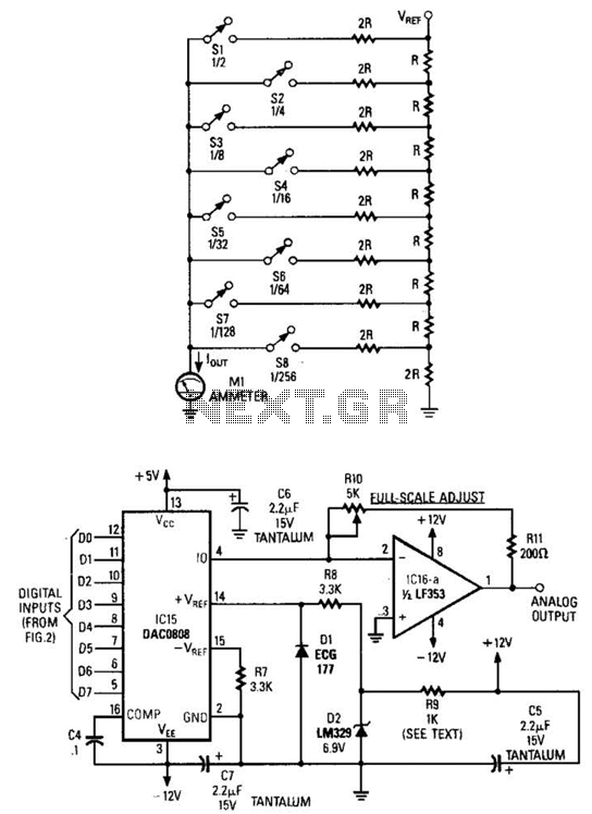
Figure A illustrates an R/2R resistor ladder. Each closed switch increases the current flow. A basic channel A/D converter is depicted in Figure B. The voltage reference (D2) is shared across all channels, although the value of the dropping...
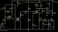
The TV transmitter described utilizes UK standard 1 FM modulation for sound and PAL modulation for video. The audio signal to be modulated is first amplified using transistor Q1 and its associated components. Transistor Q2 serves dual functions: generating...
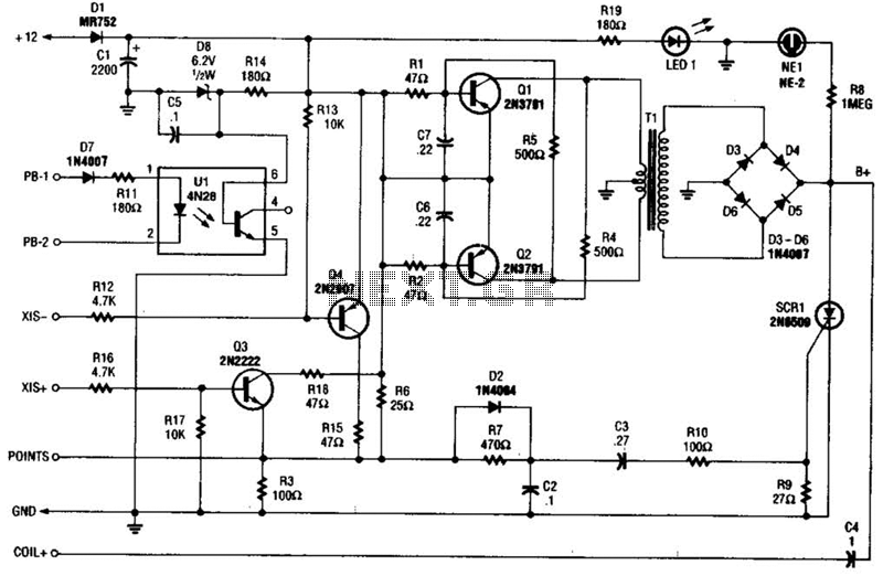
At the core of the CD4-MX is an astable multivibrator, constructed using transistors Q1 and Q2, which drives step-up transformer T1. The output from T1 is rectified by diodes D3 to D6 and utilized to charge capacitor C4. Upon...
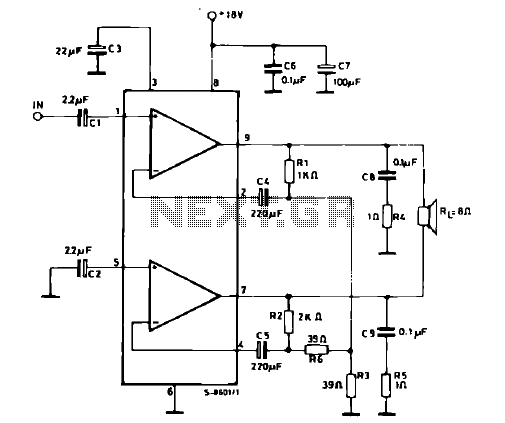
The schematic illustrates a 12 W Bridge Amplifier circuit diagram utilizing the TDA2007A, a class AB dual audio power amplifier. This amplifier is specifically designed for stereo applications in music centers, television receivers, and portable radios. As stated in...
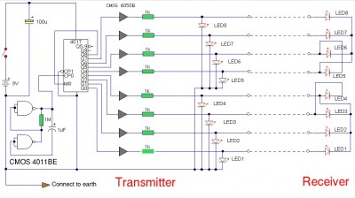
The LAN tester circuit can also test cables such as telephone, coaxial, LAN, and others. This circuit uses LEDs as the main indicator device. The LAN tester circuit is designed to verify the integrity and functionality of various types of...
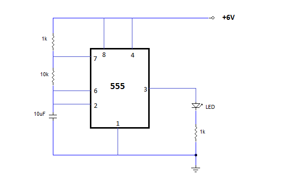
The NE555 is one of the most commonly used timer integrated circuits (ICs). It is a monolithic timing circuit capable of producing accurate and highly stable time delays or oscillations. Similar to general-purpose operational amplifiers, it is reliable, easy...