
Voice Transmitter Via FM Band 2 VHF by Hartley Oscillator

The frequency modulation (FM) voice transmitter circuit operates within the VHF (Very High Frequency) range, typically between 30 MHz and 300 MHz. This circuit is designed to modulate an audio signal, such as a voice, onto a carrier frequency, allowing for wireless transmission.
The key components of this circuit include an oscillator, a modulator, and an amplifier. The oscillator generates a stable carrier frequency within the FM band. The modulator combines the audio input with the carrier signal, varying the frequency of the carrier in accordance with the amplitude of the audio signal. This modulation technique allows for effective transmission of voice signals over the airwaves.
An important aspect of the design is the choice of components, including transistors or integrated circuits that can handle the necessary frequency range and provide adequate gain. The circuit may also include filters to eliminate unwanted harmonics and improve signal clarity. Additionally, an antenna is essential for transmitting the modulated signal effectively into the surrounding environment.
Power supply considerations are also critical, as the circuit must maintain stable operation under varying load conditions. This can be achieved through the use of voltage regulators and capacitors to stabilize the power supply.
Overall, this FM voice transmitter circuit is a versatile electronic device suitable for various applications, including amateur radio, educational projects, and short-range wireless communication. Proper tuning and alignment of the circuit are necessary to ensure optimal performance and compliance with regulatory standards for frequency usage.The circuit was designed to operate a frequency modulation voice transmitter over the FM band 2 frequency range of VHF. Transmitter an electronic device.. 🔗 External reference
Related Circuits
The range of this FM transmitter is approximately 100 meters when powered by a 9V DC supply. The circuit consists of three stages. The first stage is a microphone preamplifier. The FM transmitter circuit is designed to convert audio signals...
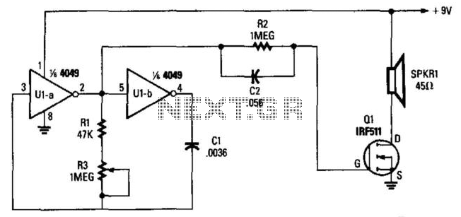
Two gates, U1A and U1B, of a 4049 hex inverter, are connected in a VFO circuit. Components R1, R3, and C1 set the frequency range of the VFO. With the given values, the circuit's output can range from a...
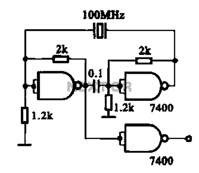
Crystal oscillator integrated circuits, specifically two diagrams of oscillator circuits with oscillation frequencies of 10 MHz and 20 MHz. Crystal oscillators are essential components in various electronic applications, providing stable frequency references for timing and synchronization purposes. The circuits presented...
This article addresses inquiries regarding a low-power FM transmitter designed to accept input from various sound sources, such as a guitar or microphone, and transmit on the commercial FM band. It is important to select an unused frequency on...
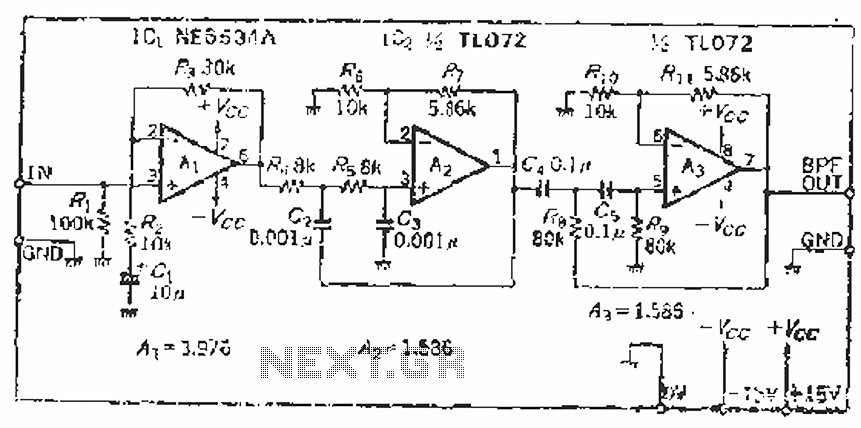
The filter incorporates a zoom function, with a front satin amplifier magnification calculated as d = 10/2.515 = 3.97, which results in a total beam compared to a 10 times magnification. The low-pass filter parameters are specified as a...

The pressure transmitter circuit data acquisition system utilizes the 1B31, an 18-bit A/D converter (AD1170), and an MCS-51 microcontroller. The configuration, as depicted in the accompanying diagram, features a full-scale output voltage of 10 mV from the pressure transmitter...