
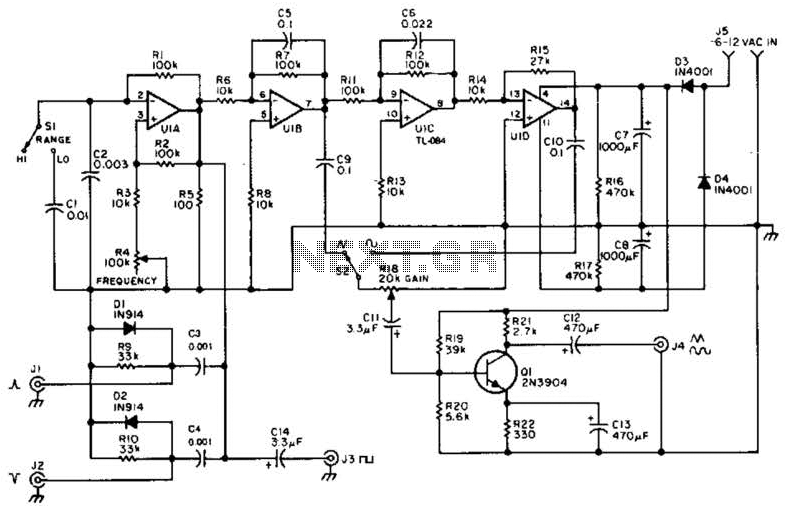
Measuring SN audio bandpass filter circuit

The described circuit features a combination of low-pass and high-pass filters, which are critical in audio and signal processing applications. The low-pass filter is designed to allow signals below a certain frequency (20 kHz) to pass while attenuating higher frequencies. The quality factor (Q) of 0.707 indicates a standard Butterworth filter configuration, which provides a maximally flat frequency response in the passband. The capacitance value of 0.001 µF (1 nF) is essential for determining the filter's cutoff frequency in conjunction with the resistance values calculated.
The resistance value Rs = 7.96 kΩ plays a significant role in establishing the filter's impedance and affects the overall gain of the circuit. The inductance value of L = 10 kΩ (A-1) = 5.86 kΩ suggests that there may be an additional element or configuration influencing the filter's behavior, possibly indicating a series or parallel arrangement with other components.
On the other hand, the high-pass filter is designed to allow signals above 20 Hz to pass while attenuating lower frequencies. The Q factor remains at 0.707, ensuring a smooth transition at the cutoff frequency. The capacitance of 0.1 µF is larger than that of the low-pass filter, which results in a different response characteristic. The resulting resistance values of Rs = Rt = 79.8 kΩ indicate a high impedance path, which can be beneficial in applications requiring minimal loading on the source signal.
Overall, the combination of these filters allows for precise control over the frequency response of the system, making it suitable for various applications in audio processing, communications, and signal conditioning. The design considerations of both filters ensure that the circuit can effectively manage the desired frequency components while suppressing unwanted noise and interference.Since the filter has a zoom function, front satin amplifier magnification such as d = 10/2. 515 = 3,97, the beam of the total, compared with 10 times magnification. Low-pass filter parameters, according to] r five = 20k Hz, Q = 0.707, mouth if taken 0. ooiuF, you can find Gong = Rs = 7.96kQ, Lu T = iokfl (A-1) = 5.86kQ. High-pass filter parameters, ugly - 20Hz, Q = 0. 707, if cd = c5 = 0.1 liF, you can find Rs = Rt = 79, fikQO
Related Circuits
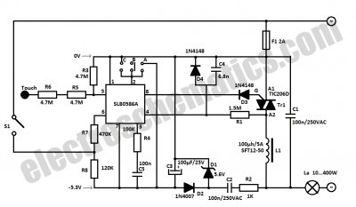
This circuit is a musical doorbell. When the button S1 is pressed, a short melody plays. If the button is pressed multiple times in quick succession or held down, a different melody is generated, and the melody plays for...
A quad op-amp serves as the core component of this function generator. U1A produces a square wave, which is outputted to J8. J1 and J2 are pulse outputs derived from differentiating the square wave. The integrator U1B creates a...
This light dimmer control features active timing capacitor reset or AC line zero-crossing synchronization. The 13 additional components are common and cost less than $2. Performance at the low end is exceptionally smooth and snap-free, even better than the...
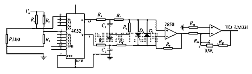
A company has developed an intelligent temperature monitoring system using the ATMET 89C51 microcontroller. This system automatically records temperature data for a three-phase power supply, including high temperature and other relevant data, functioning as a black box. The ATMET...
While developing an infrared (IR) extender circuit, a method was needed to measure the relative intensities of different infrared light sources. This circuit utilizes an SFH2030 photodiode as the infrared sensor. A CA3140 MOSFET operational amplifier is employed in...
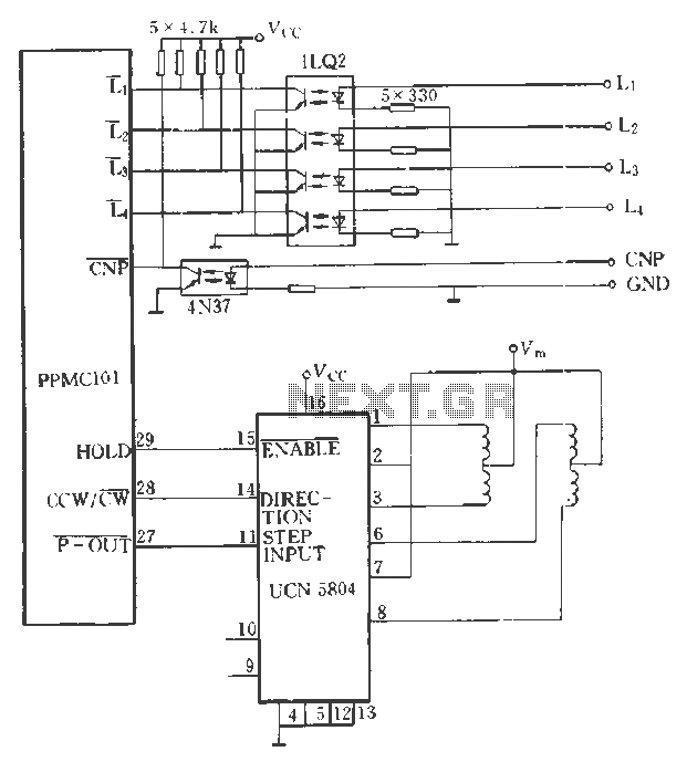
The PPMC external UChl 5804 demonstrates a four-phase stepping motor drive integrated circuit (IC) that is depicted in a downward motion. It utilizes the P-OUT, counterclockwise (ccw) / clockwise (cw), and HOLD outputs. The UCN5804 pins 9 and 10...