
Bridge rectifier circuit in the electronic ballast application circuit

The bridge rectifier circuit is a crucial component in electronic ballast applications, primarily utilized for converting alternating current (AC) to direct current (DC). This conversion is essential for powering various electronic devices, particularly in lighting systems where precise control of current is necessary for optimal performance.
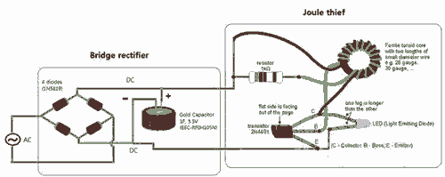
The typical configuration of a bridge rectifier consists of four diodes arranged in a bridge topology. This arrangement allows both halves of the AC waveform to be utilized, effectively doubling the output voltage and improving efficiency. The diodes are connected in such a way that during the positive half-cycle of the AC input, two diodes conduct and allow current to flow through the load in one direction. During the negative half-cycle, the other two diodes conduct, again allowing current to flow through the load in the same direction. This results in a pulsating DC output.
In an electronic ballast application, the bridge rectifier is often followed by a smoothing capacitor, which serves to reduce the ripple voltage in the output. This capacitor stores energy during the peaks of the rectified voltage and releases it during the troughs, providing a more stable DC voltage to the subsequent circuitry. Additionally, voltage regulators may be employed to further stabilize the output voltage and ensure compatibility with the electronic components being powered.
The design of the bridge rectifier must take into account the maximum input voltage and current ratings, as well as the thermal management of the diodes to prevent overheating. Proper selection of diode specifications, such as reverse voltage rating and forward current rating, is essential to ensure reliable operation under varying load conditions.
Overall, the bridge rectifier circuit plays a vital role in the functionality of electronic ballasts by enabling efficient energy conversion and stable power delivery to lighting systems, thereby contributing to energy savings and enhanced performance in lighting applications. Bridge rectifier circuit in the electronic ballast application circuit
Related Circuits
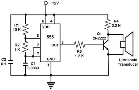
The circuit utilizes a 555 timer integrated circuit (IC) configured as an astable multivibrator, which generates a continuous signal at a specific frequency as long as its reset pin (pin 4) is held high. The ultrasonic transducer employed in...
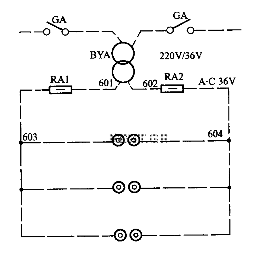
APM-81 lift includes the main circuit, safety circuit, and brake circuit. The APM-81 lift system is designed with a comprehensive electrical architecture that integrates a main circuit, a safety circuit, and a brake circuit, ensuring reliable operation and enhanced safety...
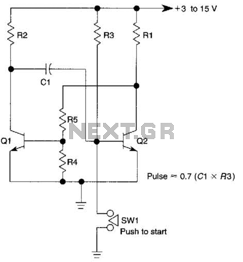
This circuit is activated when switch SW1 is pressed, grounding the base of transistor Q2. The pulse rate is approximately equal to 0.7 multiplied by the product of resistor R3 and capacitor C1. The described circuit features a transistor Q2,...

Figure 1 shows the block diagram of a direct conversion RF receiver—the receiver demodulates an RF carrier directly into a baseband signal without an intermediate frequency down-conversion (a zero IF receiver). The antenna, shared by both the transmitter and...
This circuit will impose a maximum slew rate on a signal; positive and negative rates can be independently controlled. The circuit is useful in servo applications where the error signal needs to be limited to be within the power...
Breathe down and come out on the bright flashlight. In order to promote the voltage, pieces of a highly skilled Joule thief circuit have been used. The Joule thief circuit is a minimalist, low-power boost converter designed to extract energy...