
Voltage Controlled Oscillator

In the design of a voltage-controlled oscillator, the choice of components is critical for achieving the desired frequency stability and modulation characteristics. The LC tank circuit in linear VCOs typically consists of an inductor (L) and a varactor diode (D) in parallel, which allows for precise frequency tuning by varying the reverse bias voltage applied to the varactor. The relationship between the capacitance of the varactor and the voltage across it is given by the varactor's capacitance-voltage (C-V) curve, which is essential for determining the frequency range of the oscillator.
In relaxation-type VCOs, the timing characteristics are primarily determined by the RC time constant of the charging and discharging circuit. The choice of resistor (R) and capacitor (C) values influences the frequency of oscillation and the shape of the output waveform. For instance, a larger capacitor will result in a slower charge and discharge cycle, producing a lower frequency output. The active element, such as a UJT or monolithic IC like the LM566, provides the necessary switching action to generate the waveform.
The LM566 IC, in particular, is advantageous due to its versatility and ease of use. It incorporates internal timing circuitry that simplifies the design process. The output frequency can be finely tuned by adjusting the external resistor and capacitor values, allowing for a wide range of applications. The IC's ability to generate both square and triangular waveforms simultaneously makes it suitable for various modulation schemes.
Overall, the voltage-controlled oscillator is a fundamental component in many electronic systems, enabling frequency modulation and signal generation with high precision and stability. Understanding the operational principles and design considerations of VCOs is essential for engineers working in communications, signal processing, and related fields.Voltage controlled oscillator is a type of oscillator where the frequency of the output oscillations can be varied by varying the amplitude of an input voltage signal. Voltage controlled oscillators are commonly used in frequency (FM), pulse (PM) modulators and phase locked loops (PLL).
Another application of the voltage controlled oscillator is th e variable frequency signal generator itself. Block diagram of a typical voltage controlled oscillator is shown below. Voltage controlled oscillators can be broadly classified into linear voltage controlled oscillators and relaxation type voltage controlled oscillators. Linear voltage controlled oscillators are generally used to produce a sine wave. In such oscillators an LC tank circuit is used for producing oscillations. An active element like transistor is used for amplifying the output of the LC tank circuit, compensating the energy lost in the tank circuit and for establishing the necessary feedback conditions.
Here a varactor (varicap) diode is used in place of the capacitor in the tank circuit. Varactor diode is type of semiconductor diode whose capacitance across the junction can be varied by varying the voltage across the junction. Thus by varying the voltage across the varicap diode in the tank circuit, the output frequency of the VCO can be varied.
Relaxation type voltage controlled oscillators are used to produce a sawtooth or triangular waveform. This is achieved by the gradual charging and sudden discharge of a capacitor connected appropriately to an active element (UJT, PUT etc) or a monolitic IC (LM566 etc).
Now a days relaxation type VCOs are generally realized using monolithic ICs. LM566 is a monolithic voltage controlled oscillator from National semiconductors. It can be used to generates square and triangle waveforms simultaneously. The frequency of the output waveform can be adjusted using an external control voltage. The output frequency can be also programmed using a set of external resistor and capacitor. Typical applications of LM566 IC are signal generators, FM modulators, FSK modulators, tone generators etc. The LM566 IC can be operated from a single supply or dual supply. While using single supply, the supply voltage range is from 10V to 24V. The IC has a very linear modulation characteristics and has excellent thermal stability. The circuit diagram of a voltage controlled oscillator using LM566 is shown in the figure below. Resistor R1 and capacitor C1 forms the timing components. Capacitor C2 is used to prevent the parasitic oscillations during VCO switching. Resistor R3 is used to provide the control voltage Vc. Triangle and square wave outputs are obtained from pins 4 and 3 respectively. Output frequency of the VCO can be obtained using the following equation: 🔗 External reference
Related Circuits
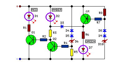
This circuit monitors battery voltage and features a three-LED display. By connecting this circuit to the battery of a vehicle, users can easily determine the approximate voltage at a glance. The battery voltage monitoring circuit utilizes a simple yet effective...
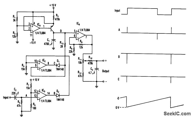
When the input transitions from low to high, a narrow positive pulse is generated at point A. This pulse results in a -13 V level at point B, which causes diode D2 to turn off. Consequently, the V+ voltage...
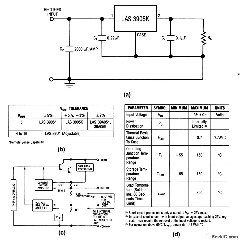
The LAS3905 series voltage regulators are integrated circuits (ICs) that incorporate all components required for linear voltage regulation, including safe-area protection, thermal overload protection, and current limiting. The output voltage and tolerance for the various LAS3905 part numbers are...
The circuit was designed based on the functionality of an operational amplifier to create a Wien bridge oscillator that generates sine waves in the frequency range of 15 Hz. The Wien bridge oscillator is a type of electronic oscillator that...
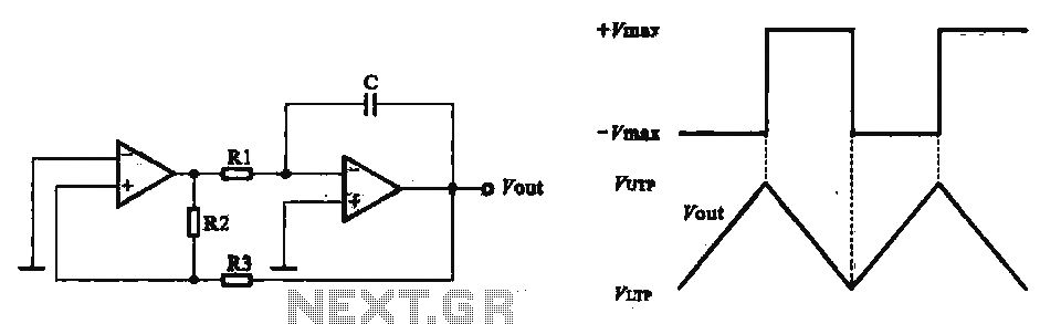
This circuit utilizes two operational amplifiers configured as triangular wave oscillators. It demonstrates a practical application of a relaxation oscillator that employs a voltage comparator to execute the switching function. The schematic in FIG. 2 illustrates the composition of...
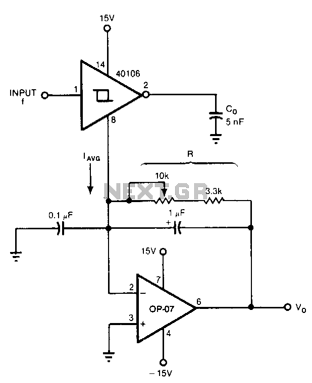
Six components can configure a circuit whose output voltage is proportional to its input frequency. The average current from the ground pin 8 of the 40106 Schmitt trigger inverter is linearly dependent on the frequency at which the capacitor...