
Voltage Controlled Oscillator with Varactor

The Voltage Controlled Oscillator (VCO) circuit described operates using a Hartley oscillator configuration, which is a type of LC oscillator known for its simplicity and effectiveness in generating oscillations. In this circuit, the frequency of oscillation is primarily determined by the inductance (L1) and capacitance (C1) components used in the design.
The Hartley oscillator consists of two inductors and one capacitor. In this configuration, the inductors are typically connected in series or parallel to form a feedback loop that sustains oscillation. The frequency of the output signal can be expressed using the formula:
\[ f = \frac{1}{2\pi\sqrt{L_{total} \cdot C}} \]
where \( L_{total} \) is the effective inductance of the inductor network and \( C \) is the capacitance. In a VCO, the capacitance (C1) can be varied by using a variable capacitor or a combination of fixed and variable capacitors to achieve a range of frequencies. This allows for dynamic control of the output frequency based on the input voltage.
The circuit typically includes a transistor or operational amplifier that amplifies the oscillation signal, along with additional components for biasing and stability. The output of the VCO can be used in various applications, including frequency modulation, phase-locked loops, and signal generation for communication systems.
In practice, careful selection of the values for L1 and C1 is critical to achieving the desired frequency range and stability of the oscillator. Additionally, the circuit may incorporate filtering and buffering stages to ensure that the output signal maintains integrity and is suitable for further processing or transmission.This is a Voltage Controlled Oscillator? (VCO) circuit. This circuit is based on Hartley oscillator. The frequency depend on the value of C1 and L1. The. 🔗 External reference
Related Circuits
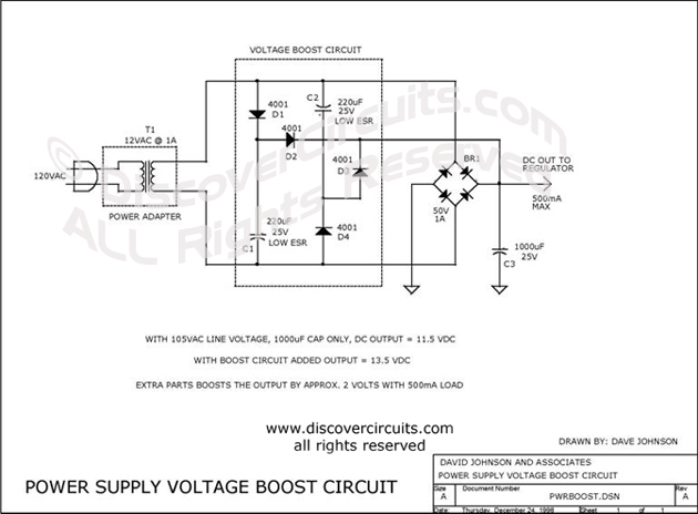
This circuit incorporates capacitors and diodes into a conventional transformer-based series regulator circuit to enhance its operational range. It ensures regulation under low line voltage conditions and can extract additional power from a standard plug-in power supply. The described circuit...
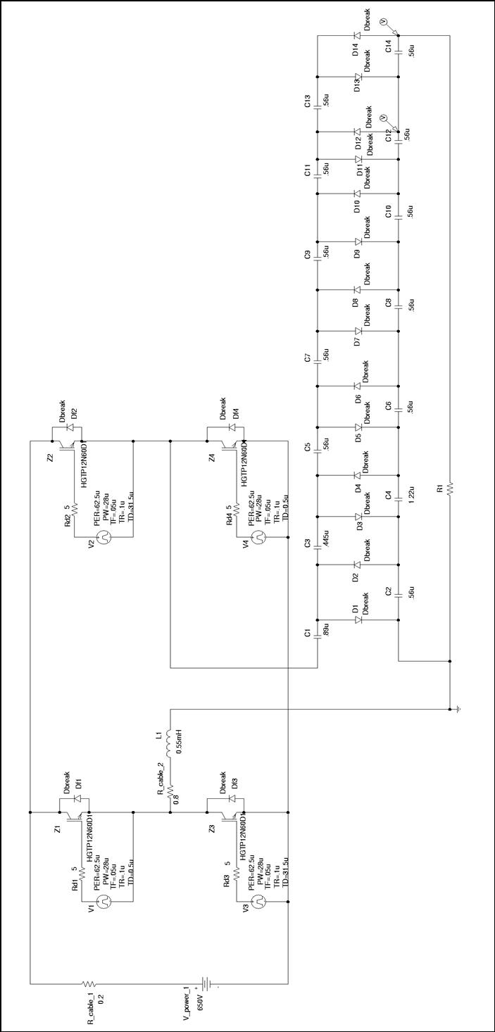
Thesis by Rafael Bräg at the University of Canterbury, New Zealand, in cooperation with the Universität Karlsruhe, Institut Elektrotechnik und Hochspannungstechnik. The thesis presents a comprehensive study conducted by Rafael Bräg, focusing on advancements in the field of electrical engineering....
Voltage regulator ICs with 3 pins, from the LM7805 and LM7812 series, are excellent for use in voltage regulator circuits. If higher currents are required, up to... Voltage regulator integrated circuits (ICs), specifically from the LM7805 and LM7812 series, serve...
The Automatic Forklift System (AFS) is engineered to enhance the safety and efficiency of warehouse stocking processes. Traditional manually operated forklifts pose injury risks to employees. The Automatic Forklift System (AFS) aims to mitigate these hazards. The Automatic Forklift System...
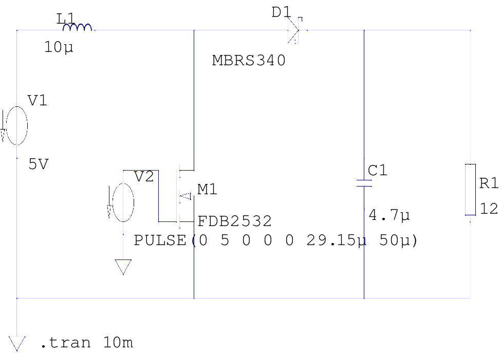
The supply voltage is 5V, and the goal is to increase it to 12V with a load current of 1A, resulting in an output power of 12W. A switching frequency of 20kHz has been selected, requiring a duty cycle...
This CMOS square-wave oscillator utilizes the 4047 multivibrator circuit, suitable for both monostable (one-shot) and astable applications. In the provided configuration, the 4047 operates as an astable multivibrator. The circuit features three outputs from the 4047, with the first...