
Video/Audio Switcher Circuit

The channel selector circuit is designed to facilitate the selection of video and stereo audio signals from three distinct input sources. This functionality is essential in applications where multiple signal sources need to be managed efficiently, such as in home theater systems or professional audio-visual setups.
The core of the circuit involves the use of analog switches or multiplexers that route the selected input to the output based on user control. Each of the three input sources is connected to the switch, allowing for seamless transitions between them without the need for physical reconnections. The control mechanism can be implemented using a manual switch or a microcontroller for automated selection.
To ensure high-quality signal integrity, the circuit should be implemented on a printed circuit board (PCB) featuring a substantial ground plane. This ground plane serves to reduce electromagnetic interference (EMI) and minimizes noise pickup, which is critical for maintaining the clarity of both audio and video signals. Proper layout techniques should be employed, including short trace lengths for signal paths and the strategic placement of decoupling capacitors near power supply pins to further mitigate noise.
Additionally, the use of high-quality components, such as low-on-resistance switches and capacitors with low equivalent series resistance (ESR), will contribute to the overall performance of the channel selector. The circuit should also incorporate appropriate filtering techniques to eliminate any unwanted frequencies that may affect audio and video quality.
In summary, the design of the channel selector circuit must prioritize signal integrity and noise reduction while providing a user-friendly interface for selecting between multiple sources. This approach will ensure optimal performance in a variety of audio-visual applications. This channel selector selects video and stereo audio from any one of three different sources. The circuit should be constructed on a PC board with plenty of ground plane to minimize noise.
Related Circuits
This circuit design is intended for conducting harmless experiments with high-voltage pulses, functioning similarly to an electrified fence generator. The pulse repetition frequency (PRF) is determined by the time constant of the resistor-capacitor network R1-C3 in the feedback loop...
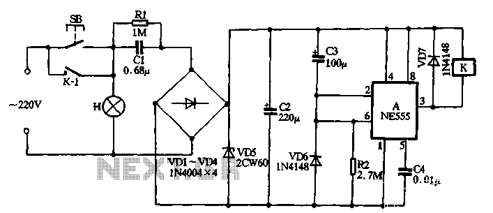
The NE555 push-button delay lamp circuit is illustrated in Figure 3-5. This circuit features several components, including a power supply and relay control system. Typically, the switch SB and normally open relay contacts K1 are in an open state,...
Adding a discharge path to the upper MOSFET of a cascode circuit significantly reduces the unavoidable Miller effect, thereby enhancing the Power Factor Correction (PFC) performance of a power supply's front end. In a cascode configuration, the upper MOSFET is...
Working with lasers can be enjoyable and intriguing, but it can also be costly. High voltage power supplies for laser tubes are often more expensive than the tubes themselves. However, this power supply can be constructed using common components...
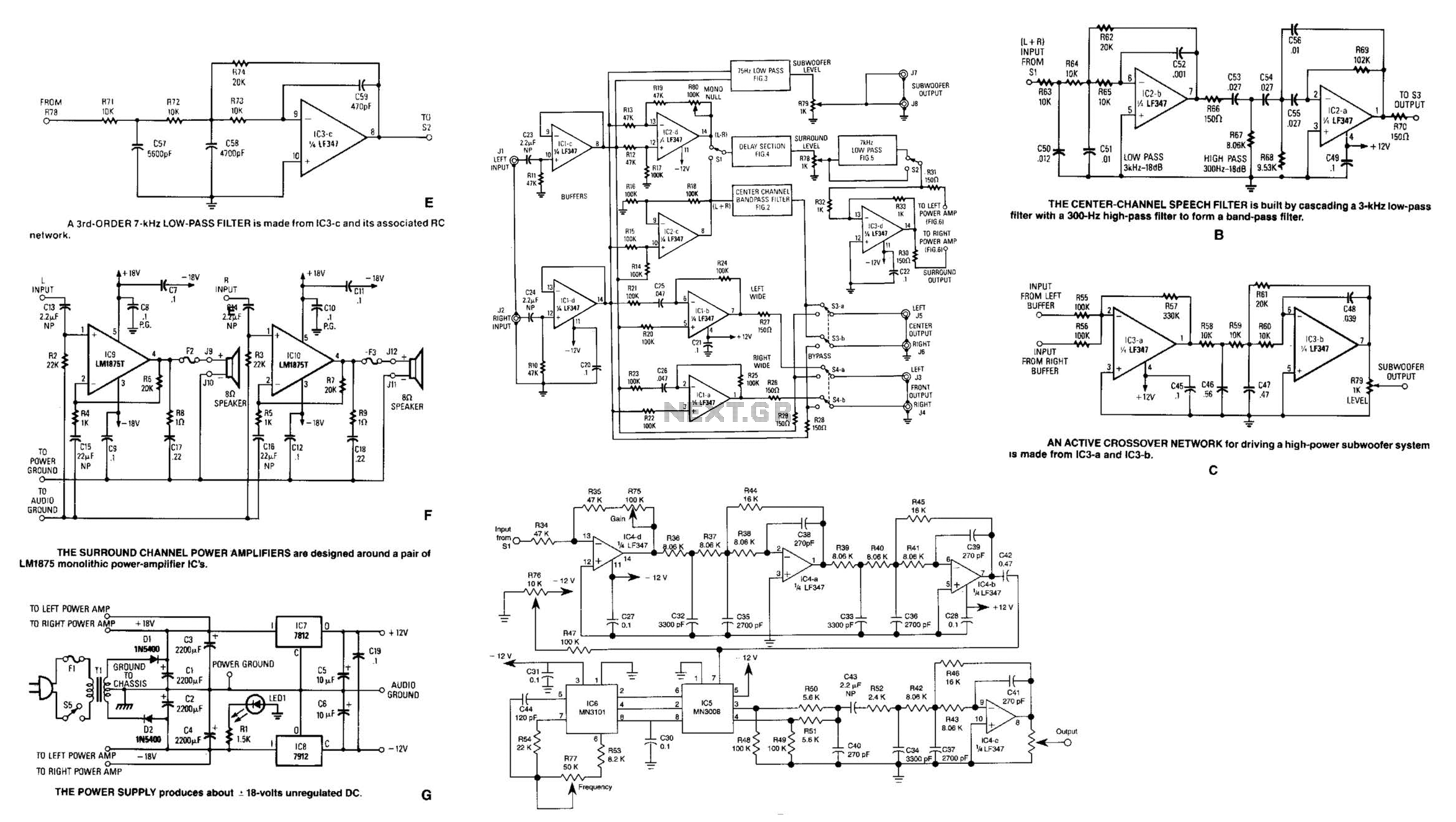
Referring to the simplified schematic in A, the audio frequency generator (AFG) consists of 10 relatively simple circuit elements. IC1-c and IC1-d are configured as unity-gain non-inverting buffer amplifiers. The summing amplifier, IC2-c, combines equal amounts of the left...
The following circuit illustrates the sensor circuit of an analog line follower robot. Features include control by a microcontroller and a sensor circuit. The sensor circuit for an analog line follower robot is designed to detect the presence of a...