
Voltage detector by IC TL431

The circuit is designed to monitor pressure levels by utilizing the TL431, a programmable shunt voltage reference. The TL431 can be configured to operate as a voltage comparator, which is essential for this application. It compares the voltage derived from a pressure sensor against a predefined reference voltage.
The circuit typically includes a pressure sensor that converts the pressure level into an equivalent voltage signal. This voltage is then fed into the non-inverting input of the TL431. The inverting input is connected to a voltage divider that sets the reference voltage. When the sensed voltage exceeds the reference voltage, the TL431 activates its output, which can be used to trigger an alarm, activate a relay, or send a signal to a microcontroller for further processing.
Power supply requirements for the circuit are modest, with a 5-volt supply being sufficient for operation. Proper decoupling capacitors should be included near the power supply pins of the TL431 to ensure stable operation and to filter out any noise present in the supply line.
Additional components may be included in the design, such as resistors for the voltage divider, capacitors for stability, and possibly a transistor for driving higher loads. The output stage can be tailored according to the specific application needs, allowing for versatility in implementation.
This pressure level check circuit is suitable for various applications, including industrial automation, HVAC systems, and safety monitoring systems, where maintaining specific pressure levels is critical.This be simple check pressure level circuit, with integrated number circuit TL431. When use power supply 5Volt in digital circuit. The general feeding signal.. 🔗 External reference
Related Circuits
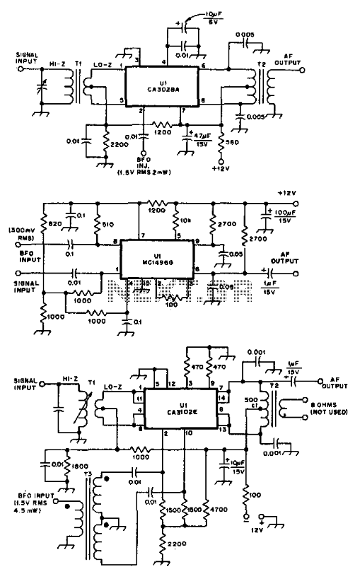
These product detectors utilize integrated circuit (IC) devices. They are capable of detecting single sideband (SSB) and continuous wave (CW) signals. The circuits are designed to operate effectively up to frequencies of 20 or 30 MHz. T3 in the...
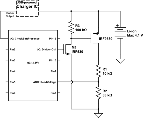
Currently using the PIC24FJ128GA010, there is a plan to utilize an Input/Output port to connect a 4.2 V LiPo battery and monitor the voltage to ensure it does not drop below 3.7 V. It is advised to avoid digital...

A simple metal detector circuit diagram and schematic using a single transistor and a radio. This metal detector/sensor project is easy to make and is an application of a Colpitts oscillator. The metal detector circuit utilizes a single transistor in...
This circuit is designed to signal the exceeding of a fixed threshold in room noise through a flashing LED. Three fixed levels are selectable: 50, 70, and 85 dB. Two operational amplifiers provide the necessary gain for sounds captured...
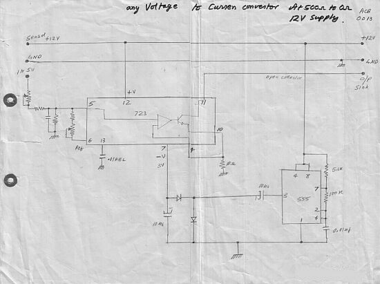
This circuit converts a voltage control output from a process controller into a current control signal, which is necessary when an AC drive or valve requires a current control signal. It operates as a three-wire voltage-to-current loop converter. A...
.png)
This document describes a simple engineering project circuit for a mobile cell phone detector (sniffer). This compact mobile communication detector can sense the presence of a mobile device, making it suitable for preventing mobile phone usage in private spaces,...