
Voltage to Current Convertor using LM723 Project PCB

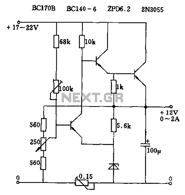
The circuit effectively utilizes the LM723 voltage regulator, which is configured as an operational amplifier in this application. The input voltage range of 1-5 V DC is crucial for the operation, as it is the control signal that dictates the output current. The attenuation process is essential for ensuring that the input voltage is scaled appropriately to match the desired output current range of 4-20 mA, which is a standard for many industrial control systems.
The open collector configuration of the output allows for flexibility in connecting multiple devices in series without the risk of affecting the operation of each device. The current sink design ensures that the output current remains constant, regardless of variations in load, as long as the input voltage remains within the specified range.
The operation of the LM723 as an op-amp involves feedback mechanisms that maintain the desired output. The calibration process through the attenuator enables precise adjustments to be made, ensuring that the output is accurately reflective of the input voltage. This is particularly important in applications where accurate control signals are necessary for the operation of devices such as valves or AC drives.
Furthermore, the ability to connect up to three instruments with a supply voltage of 24 V enhances the versatility of the circuit, making it suitable for various applications in industrial settings. The inclusion of a connection to pin 6 for converting a 0-1 V input to a 4-20 mA output adds another layer of functionality, allowing the circuit to accommodate different input signal types.
In summary, this voltage-to-current loop converter circuit is a robust solution for converting control signals in various industrial applications, providing reliable and accurate current outputs for effective control of AC drives, valves, and other instrumentation.Circuit This Circuit converts a voltage control output from a Process Controller to be converted into a Current Control if the AC-Drive or Valve needs a Current Control Signal. This is a three wire voltage to current loop converter. The 1-5 V DC is attenuated and fed to pin 5 LM723 opamp section which tries to maintain the same voltage at pin 10 a
cross the 10 E, thereby producing a open collector constant current sink proportional to the 1-5V input. By trimming the attenuator you can scale- calibrate 1-5V input to 4-20mA output for looping many instruments in series, like a controller, recorder or PLC.
With a supply voltage upto 24V, three instruments can be looped. The connection to pin 6 is required to convert 0-1 input to 4-20mA. 🔗 External reference
Related Circuits
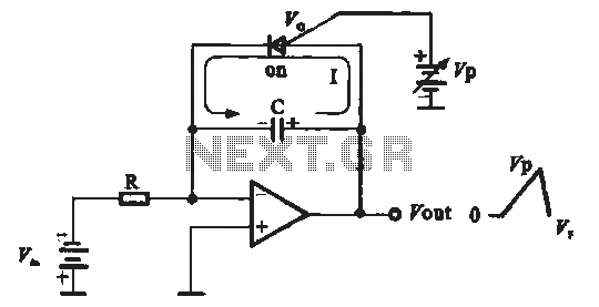
A sawtooth voltage-controlled oscillator operates by first generating a negative potential maximum at the output of the comparator. This output is then fed to the inverting input terminal through resistor R1, which is part of the relaxation oscillator. The...
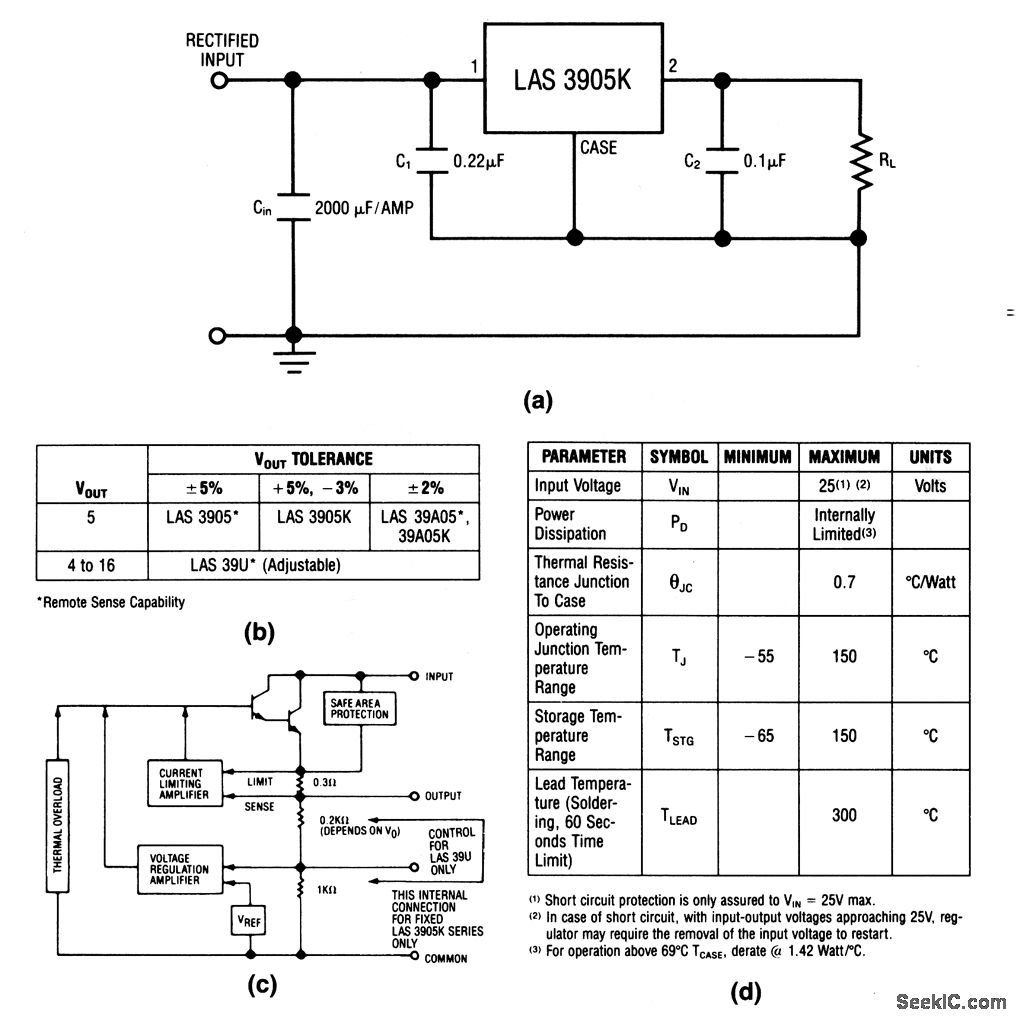
The LAS3905 series voltage regulators are integrated circuits (ICs) that incorporate all components required for linear voltage regulation, including safe-area protection, thermal overload protection, and current limiting. The output voltage and tolerance for the various LAS3905 part numbers are...
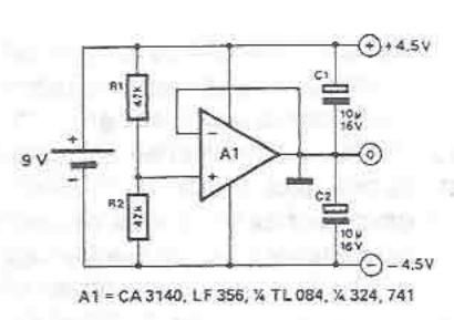
A symmetrical power supply can be designed using this circuit diagram. This symmetrical power supply is constructed with a simple operational amplifier and some classic electronic components. Resistors R1 and R2 form a high impedance voltage divider. The operational...
This light dimmer control features active timing capacitor reset or AC line zero-crossing synchronization. The 13 additional components are common and cost less than $2. Performance at the low end is exceptionally smooth and snap-free, even better than the...
The circuit output voltage can be continuously adjusted from zero to its maximum value. The baseline is established by a constant current sourced from the auxiliary power supply circuit. The reference current of 500 microamperes can be fine-tuned to...
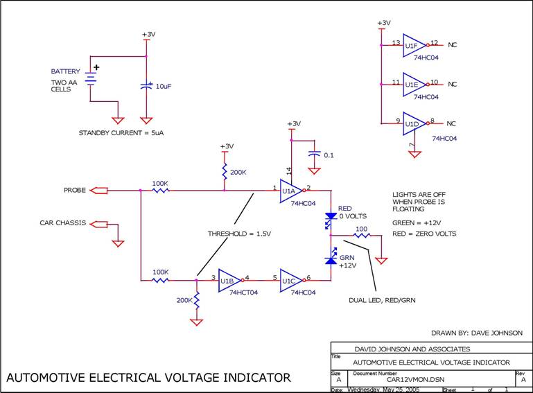
When troubleshooting the 12V electrical system of an automobile, it is beneficial to have a simple voltage indicator tool instead of a voltmeter. This electronic circuit is powered by two AA batteries or two N cells, providing sufficient energy...