
Voltage Doubler Supply Circuit

The voltage doubler circuit is designed to convert a lower input voltage into a higher output voltage using a combination of diodes and capacitors. In this circuit, the step-down transformer (T1) provides an input voltage of 12 volts at a current rating of 1 ampere.
The operation of the voltage doubler can be understood in two phases. During the first half of the AC cycle, the transformer outputs a positive voltage, which forward-biases diode D1. This allows current to flow through D1 and charge capacitor C1 to the peak voltage of the transformer output, effectively storing energy. At the same time, diode D2 is reverse-biased and does not conduct.
In the second half of the AC cycle, the transformer output becomes negative. This reverse-biases diode D1, preventing any discharge from capacitor C1. However, diode D2 becomes forward-biased, allowing capacitor C2 to charge to a voltage that is the sum of the transformer output voltage and the voltage across capacitor C1. As a result, capacitor C2 stores a voltage that is approximately double the peak voltage of the transformer output.
The output voltage can be taken across capacitor C2, which will be approximately 24 volts (assuming ideal components and no losses), effectively doubling the input voltage. The capacitors also play a crucial role in smoothing the output voltage, providing a more stable DC voltage for downstream applications. Proper selection of the diodes and capacitors is essential to ensure efficient performance and reliability of the voltage doubler circuit. The voltage doubler is built around a pair of diodes (Dl and D2) and a pair of capacitors (CI and C2) that are fed from, in this ease, a 12-V, 1-A step-down transformer (Tl).
Related Circuits
If a page name is not selected by pressing the button, the previously selected page name continues to be used. The value is stored in EEPROM and may be changed at any time. When the unit is first powered...
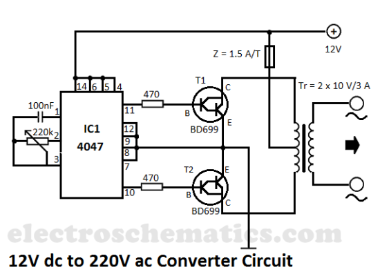
This DIY 12V to 220V voltage converter is built with a CMOS 4047, which serves as the main component for transforming 12V DC into 220V AC. The 4047 operates as an astable multivibrator, generating a symmetrical rectangular signal at...
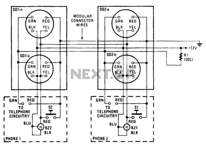
An intercom utilizing dual-modular wall jacks is depicted in this circuit. If the wires are accessible in the home telephone cable, this system can be installed with minimal difficulty. The intercom system described employs dual-modular wall jacks, which are standard...
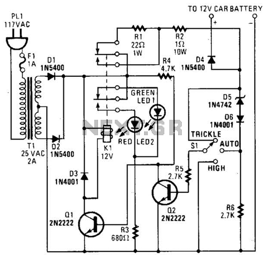
The circuit is capable of supplying either a trickle charge (50 mA) or a high-current charge (1 A). Users can select either charging method or an automatic mode that initially trickle charges a battery if it is particularly low...
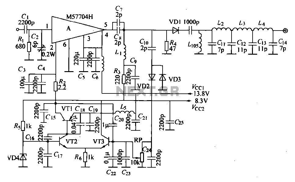
The FM radio transmitter is a high-frequency amplifier circuit that utilizes the Mitsubishi frequency set, specifically the M57704H discharge path. It operates within the frequency range of 457-458 MHz and has a transmission power of 5 watts. As illustrated...
Another unit of graphic equalizer with five bands. The primary distinction from other circuits is the use of transistors instead of integrated circuits (ICs), and the power supply operates at +/- 24V DC, which ensures low distortion and greater...