
Telephone Intercom Circuit

The intercom system described employs dual-modular wall jacks, which are standard connectors commonly used in telecommunications. The use of these jacks allows for easy connectivity and installation, particularly in residential settings where existing telephone wiring can be repurposed.
The circuit typically consists of two main components: the intercom units and the dual-modular wall jacks. Each intercom unit is equipped with a microphone and a speaker, enabling two-way communication. The dual-modular wall jacks serve as the interface points where the intercom units connect to the existing telephone wiring.
To install the system, the existing telephone cables, which usually contain multiple pairs of wires, can be utilized. The intercom units are connected to the appropriate pairs of wires at each wall jack. This setup not only simplifies the installation process but also minimizes the need for additional wiring, making it a cost-effective solution for home communication.
The intercom system can be powered through the existing telephone line, eliminating the need for separate power supplies. This feature enhances the convenience of the installation, as it reduces the complexity and potential points of failure in the system.
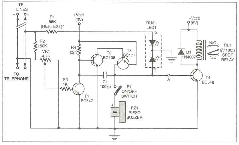
In summary, the intercom using dual-modular wall jacks is a practical solution for home communication, leveraging existing infrastructure to provide a straightforward installation process. The design ensures that users can easily communicate across different rooms without the need for extensive modifications to their home wiring. An intercom using dual-modular wall jacks is shown in this circuit. If the wires are available in the home telephone cable, this system can be installed with little trouble.
Related Circuits
This is a voltage converter designed to output a voltage range of ±1.25 to ±30V from an input voltage of ±35V. A three-terminal voltage regulator is utilized to achieve the desired voltage transformation in this unit. The voltage converter employs...
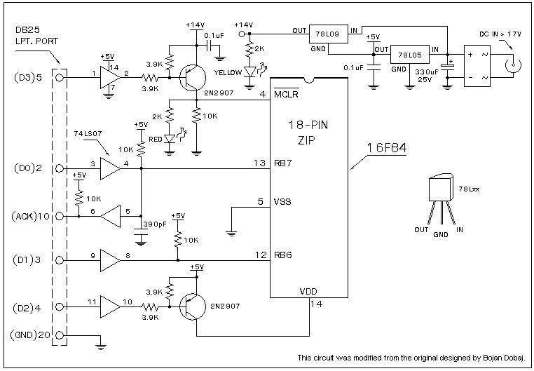
A universal Windows-based software designed to work with any serial programmers for the PIC16F84, known as WPicProg16 V1.20. It is recommended to build this programmer before starting various interesting projects with the F84. Some PIC programmers support in-circuit programming,...
Multipurpose circuit for telephone. This add-on device for telephones can be connected in parallel to the telephone instrument. The circuit provides audio-visual indication of on-hook. This multipurpose circuit serves as an enhancement for standard telephone systems by providing both audio...
One of the major problems that must be addressed in electronic circuit design is the generation of low voltage DC power supply from mains power to energize the circuit. In electronic circuit design, the conversion of mains AC voltage to...
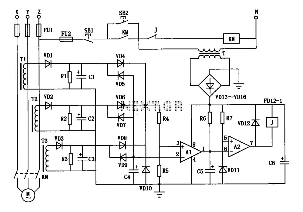
A current three-phase motor phase protection circuit is designed to detect three-phase current using homemade small current transformers T1, T2, and T3. The current signals are collected by rectifiers VD1, VD2, and VD3, while capacitors C1, C2, and C3...

FET relay circuit 2 is essentially a JS-20 time relay circuit. When the switch SA is open, the relay device KA remains in the released state. Once switch SA is closed, the delay period begins. After a specified duration,...