
Voltage Inverter

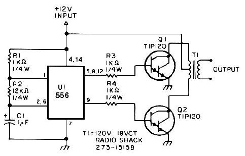
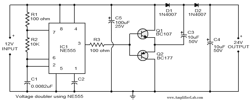
The described circuit utilizes a 555 timer configured in an astable mode to generate a square wave signal. This square wave is then applied to a transformer or an inductor, which is used to step up the voltage, allowing for the generation of a negative supply voltage from a positive input. The output from the transformer is rectified using a diode bridge, ensuring that the negative voltage is correctly oriented for use by the op-amp.
The key components include:
1. **555 Timer**: This integrated circuit serves as the oscillator, generating a continuous square wave output that drives the transformer.
2. **Transformer/Inductor**: This component is crucial for voltage inversion; it steps up the voltage from the 555 timer's output to a level suitable for the op-amp's negative supply.
3. **Diode Bridge**: Comprising four diodes, this component rectifies the AC output from the transformer into a usable DC voltage.
4. **Capacitors**: These are used for filtering the output to smooth out the rectified voltage, ensuring stable operation for the op-amp.
5. **Resistors**: These components are used to set the frequency of the 555 timer and may also be involved in biasing the op-amp.
The circuit's simplicity and low component count make it an attractive solution for applications requiring a dual supply voltage from a single battery source, such as portable audio equipment, sensor systems, and other low-power devices. The design also allows for easy adjustments to the output voltage levels by changing the transformer turns ratio or the values of the timing components in the 555 timer circuit. Overall, this circuit presents a cost-effective and efficient method for powering dual-supply operational amplifiers in various electronic applications.This simple circuit is a good solution to the powering a dual supply op amp from a single battery problem. The circuit simply takes a positive voltage and inverts it. It uses only one 555 timer and a few other passive components, so it doesn`t add much in the way of size and cost to a project.
🔗 External reference
Related Circuits
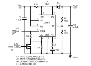
This is a 5V to 12V DC-DC step-up (boost) converter circuit designed specifically for USB-powered applications. A USB port has two current supply modes. Initially, it supplies a maximum of 100mA to the load before detecting the connected device....
This circuit incorporates a datasheet-compliant trigger signal, reversed polarity protection, an optional test button, and the capability for battery operation. It utilizes either the U1 L601E3 or MAC97A8 triac, rated for 400 V and 1 A. When U1 is...
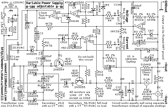
A reverse-engineered circuit diagram of a high-end commercial variable laboratory power supply. This unit is constructed using a standard operational amplifier and readily available components. While the design employs a single transformer with dual output windings, it can also...
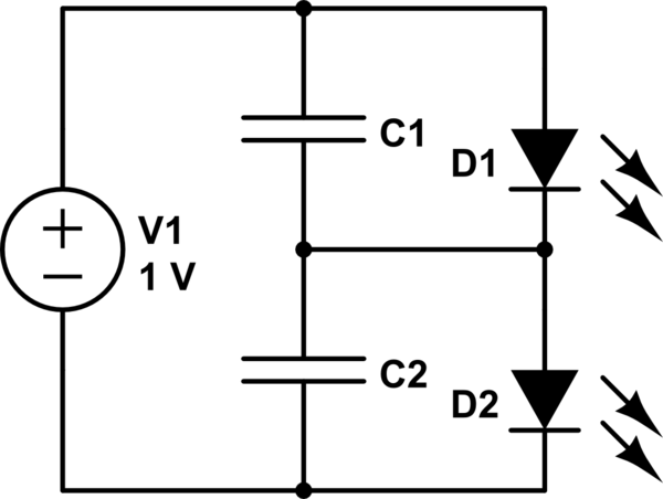
The first option is a Zener diode. There are several 2.2V Zener diodes available that could adequately protect the capacitor. However, a significant drawback is that half the energy may be wasted across the diode short. The question arises...
This low-power 25-watt power inverter circuit utilizes only nine electronic components. The inverter converts a DC input voltage ranging from 10V to 16V into a 60Hz, 115V square-wave power output, capable of powering AC electronic devices up to approximately...
Project Manager Jim Heck, G3WGM, has provided an exclusive audio interview to Bob McCreadie, G0FGX, from TX Factor, detailing the tests and potential issues involved. Membership in AMSAT-UK is available to anyone interested in amateur radio satellites or space...