
Charging a low-voltage high-C capacitor. Efficiently

In the context of voltage regulation using a Zener diode, it is essential to consider the operational characteristics and limitations of the Zener diode itself. A Zener diode operates in reverse breakdown mode, providing a stable reference voltage. When used to protect a capacitor, the Zener diode clamps the voltage to its rated value, preventing over-voltage conditions that could damage the capacitor.
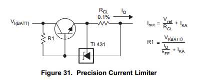
The proposed use of a high-ohm resistor in series with the Zener diode serves to limit the current flowing through the diode. This configuration can enhance efficiency by allowing more current to be directed toward charging the capacitor rather than being dissipated as heat in the Zener diode. The resistor acts as a current limiter, thus reducing the power loss associated with the Zener's operation. However, the effectiveness of this method depends on the specific circuit parameters, including the resistance value, the load characteristics, and the input voltage.
To analyze the circuit, consider a scenario where the Zener diode is rated at 2.2V, and the series resistor is chosen based on the desired current flow through the Zener. The resistor value can be calculated using Ohm's law, taking into account the supply voltage, the Zener voltage, and the load requirements.
For example, if the supply voltage is 5V and the desired current through the capacitor is 20mA, the voltage drop across the resistor would be 5V - 2.2V = 2.8V. Using Ohm's law (V = I * R), the required resistance can be calculated as R = V/I = 2.8V / 0.02A = 140Ω. A resistor value higher than this would further limit the current through the Zener diode but may also reduce the charging current to the capacitor, which could be detrimental if the capacitor needs to charge quickly.
In conclusion, while using a high-ohm resistor in series with a Zener diode can potentially improve efficiency by limiting the current through the diode, careful consideration must be given to the resistor's value to ensure that the capacitor receives sufficient current for charging. The overall effectiveness of this approach should be validated through circuit simulation or prototyping to ensure it meets the desired performance criteria.The first option is of course a zener. I actually have a bunch of 2. 2V which would protect the capacitor fine. The problem is, of course, half the energy is going to be wasted across the diode short. Is there any way I can regulate the voltage below 2. 3V without reducing the efficiency so significantly EDIT I`ve seen a few suggestions elsewhere that suggest putting a high-ohm resistor in series with the zener, presumably to minimize current through it (therefore maximising it into the capacitor). How effective would this be 🔗 External reference
Related Circuits
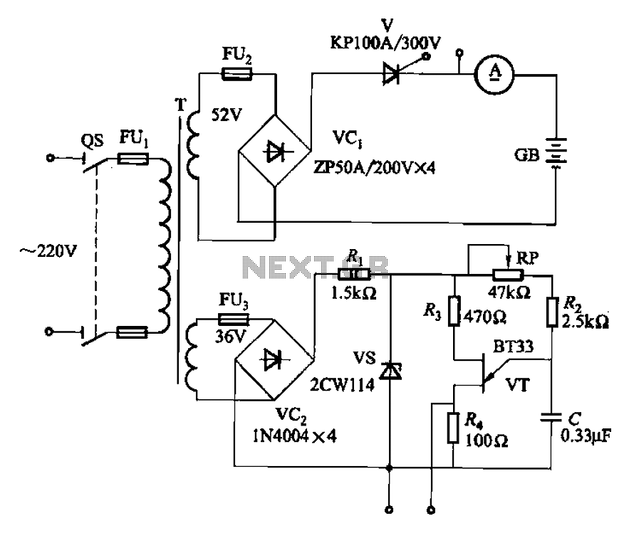
The adjustment potentiometer RP can modify the magnitude of the DC output voltage. The adjustment potentiometer, designated as RP, is an essential component in various electronic circuits, particularly in power supply systems and signal conditioning applications. It serves as a...
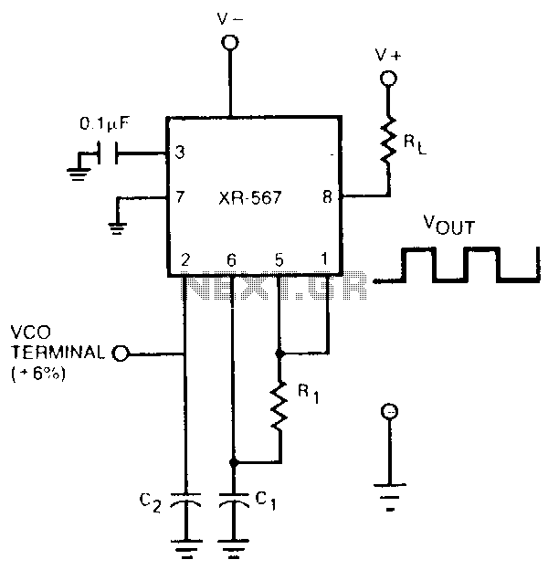
The oscillator output of the XR-567 can be amplified using the output amplifier and high-current logic output available at pin 8. In this manner, the circuit can switch 100-mA load currents without sacrificing oscillator stability. The oscillator frequency can...
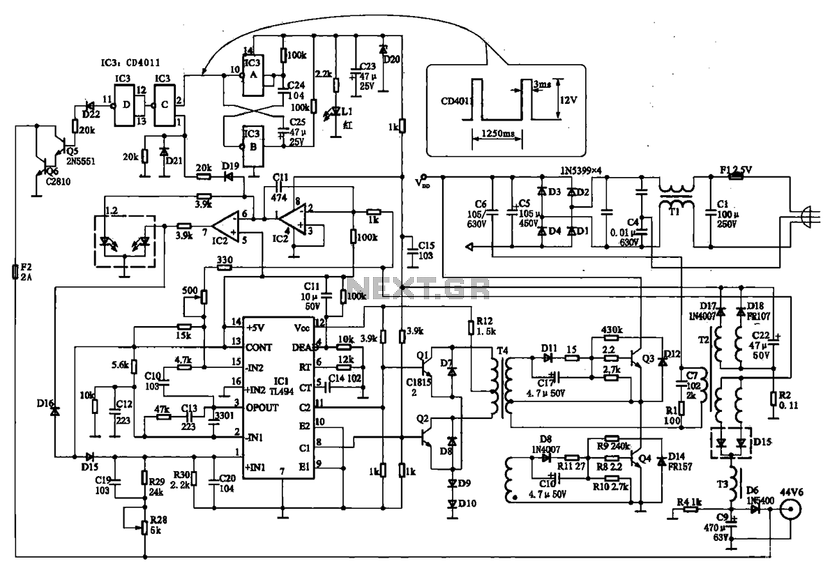
The TN-1 Intelligent Negative Pulse Charging Circuit is a sophisticated device designed for efficient battery charging. It operates as a half-bridge charger, which is a common configuration in such circuits. The negative pulse charging mechanism is facilitated by a...
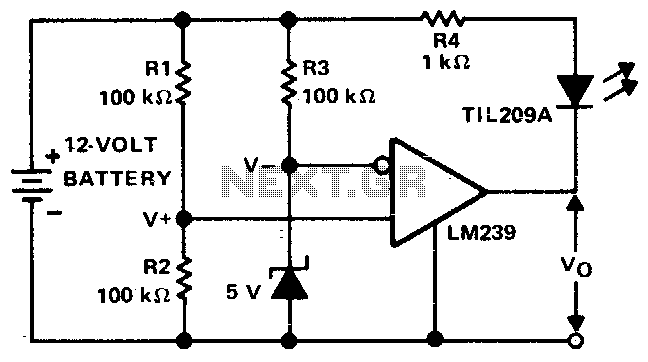
This circuit monitors the voltage of a battery and warns the operator when the battery voltage is below a preset level by turning on an LED. The values are set for a 12V automobile battery. The preset value is...
This Korean SuperCap OEM supports usage in series configurations. Consider whether the implementation will be manual or automatic, such as with a smart battery charger or a power fail backup circuit. It is essential to balance the voltage and...
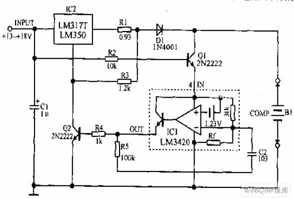
A lithium-ion battery charging circuit is illustrated above. Initially, when charging begins, if the battery voltage is below 8.4V, the output of IC1 is inactive. As a result, Q2 remains off, and the LM317 operates in constant current mode....