
battery meter for pinball machines

The circuit described is a compact battery level indicator specifically designed for use with 4.5-volt battery packs. It efficiently utilizes three LEDs to provide visual feedback on the battery status, leveraging comparators for precise voltage monitoring. The design emphasizes simplicity and ease of assembly, making it suitable for users with varying levels of electronics experience. The use of potential dividers for reference voltage generation allows for flexibility in adapting the circuit to different battery configurations. The inclusion of a quad comparator ensures accurate voltage comparisons, while the option to modify the LED indication sequence adds versatility to the design. This circuit is ideal for applications where battery monitoring is critical, such as in gaming machines, ensuring users are promptly alerted to changes in battery status.The circuit is designed to be fitted into a small box and then fitted into your backbox (the exact choice of position is yours). Only 3 wires are required one for the battery +v, one for the supply +5 volts from the MPU board or power supply and a common return to ground.
The circuit is designed for 4. 5 volt battery packs (3 cell x 1. 5 volts). The circuit gives level indication using 3 LED`s one green (good), one amber/yellow (mid) and one flashing red LED indicating low battery power 3. 2v or less approx. I think a 1. 3-1. 5 volt drop should be enough warning I can`t guage the drop-out voltage for CMOS memory standby in WPC games because of the ASIC, so, I`ve gone for what you see here.
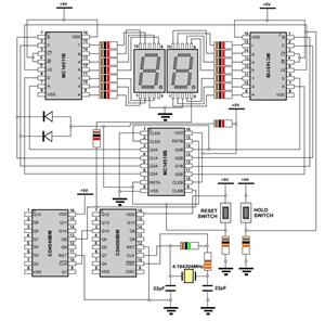
3 comparators compare the incomming battery voltage against 3 reference voltages provided by 3 potential dividers (see schematic), the 3 comparators directly drive the LED`s by sinking current to ground (internal). On power-up, the Green LED will always be on indicating good battery power. As the battery voltage drops, the amber LED will light, followed by the red flashing LED, the previous LED`s remain on until all the LED`s are lit.
I designed the circuit in this manner to cut down the component count and make the building easier. If you wish to modify the circuit so that LED`s will extinguish one after the other I suggest you use a 74HC03 quad NAND gate with open-drain outputs to sink the LED current, and, who`s input`s is switched by next comparator in sequence thereby turning the previous gate off (I would have given the schematic details here but I don`t have the IC handy to incorporate into the design at the time). IMPORTANT NOTE: If your battery pack provides 4. 21 volts or greater when new then all the leds will remain off. In most cases, new batteries do not always put out their specified voltage - a small voltage drop is usual.
The potential divers R1+R2, R3+R4 and R5+R6 provide the reference voltages. If you wish to modify the circuit to output different references, then the potential divider voltage can be given by the formula: The circuit should fit on a board 2"x 2". Build the potential divders/voltage references first, supply them with +5 volts and ground (don`t forget capacitors C1/2) and measure the output they should be approx the figures given.
Next:- add a 14 pin socket (absolutely vital) to the board and run the reference voltages to the correct pins according to the schematic, then +5 volts and ground now measure the voltages at the socket to ensure they`re present. Next:- add the 330 ohm LED current limiting resistors R10-R12 followed by the LED`s to the board (or mount them on small flyleads for fitting to the box cover).
Last but not least - add the LM or CA339 quad comparator and power up. You should have the green LED on (exception, battery >4. 21v) now rotate the 10k pot and the LED`s should light in sequence green, amber then flashing red. If they do not then power down and CHECK YOUR CONNECTIONS. If the circuit works correctly then removed the Vbat sim. and add the 3 flyleads to allow connection to the MPU board of your game. I suggest you use a red wire for +5 volts, a black wire for ground and another wire of you choice for the Vbat line. Add all the bits into a little box and mount the box onto the backbox wall. I suggest that you actually drill holes in the cover for the LED`s to protrude through, or, connect them to the board with small flyleads and glue them into the box cover.
Solder the flyleads to the MPU board with the POWER OFF. Allow the board 2 minutes before soldering in the leads as the onboard capacitors may still hold a charge. USE COMMON SENSE! don`t tap the +5 volts for the circuit from a chip leg find a free pad on the board that you can tap from.
Wire the battery power from the pack were it enters the board and return to a suitable earth point. KEEP IT NEAT! Take pride in you work make the flyleads tidy use tye-wraps and lay t 🔗 External reference
Related Circuits
Unlike a standard voltmeter, the input of an oscilloscope typically has one side (GND) connected to ground through the mains lead. This connection can lead to significant issues when the measuring probe is attached to a circuit that is...
Using LM134 and LM10 integrated circuits, a thermometer can be constructed with a sensing range of -55 to 150 °C. The ideal meter for this circuit is a 0-200 µA. The proposed thermometer circuit utilizes the LM134, a current source...
The WPG DM8168 DaVinci high-definition video System on Chip (SoC) offers multiple DVR/NVR surveillance solutions, utilizing the MT9M033 image sensor as a key component in safety monitoring systems. This solution is complemented by Conexant's line of multi-channel video surveillance...
The receiver circuit and display module will receive the high-frequency AC power cord and decode it to provide actual temperature readings using digital IC No. CD4553 (Three-digit BCD Counter IC) and IC CD4511 (BCD-to-7-Segment Latch/Decoder/Driver IC). The frequency pulses...

A 2004 Chevy Tahoe lost power while driving at 60 mph, causing the tachometer to drop to zero. The vehicle has been in the shop for three days, and the mechanics are struggling to identify the issue. They have...
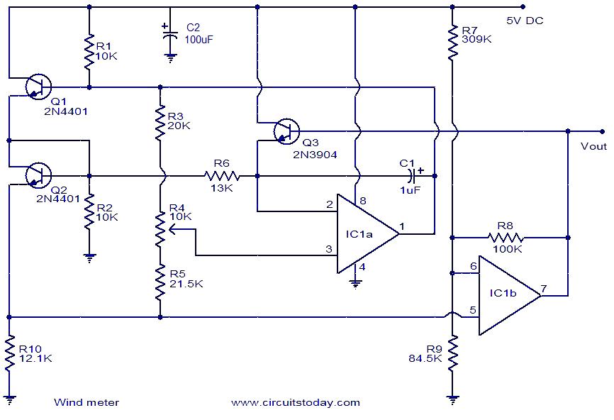
This is a simple wind meter (anemometer) circuit. While accuracy cannot be guaranteed, the circuit functions adequately. It can measure wind speeds up to 75 m/s. Transistors Q1 and Q2 are employed for wind sensing, utilizing the relationship between...