
Voltage Regulator For Cars And Motorcycles

The described regulator circuit is designed to stabilize the output voltage of an alternator by controlling the excitation of its field winding. In this configuration, the alternator's field terminal is grounded, which allows for efficient regulation of the output voltage.
The operation begins with the input voltage (V) being monitored. When this voltage exceeds a predetermined threshold, transistor Q1 becomes conductive. This conduction effectively pulls the base of transistor Q2 towards ground potential. As a result, Q2 turns off, leading to a decrease in the base current to transistor Q3. Consequently, Q3 also reduces its conduction, which directly affects the voltage applied to the alternator's field winding.
By lowering the voltage to the field, the regulator circuit effectively reduces the magnetic field strength generated by the alternator. This action helps to prevent overvoltage conditions that could potentially damage the electrical components connected to the alternator or the alternator itself.
In summary, this regulator circuit is a critical component in automotive and industrial applications, ensuring that the alternator operates within safe voltage limits while maintaining optimal performance under varying load conditions. The use of transistors for voltage regulation allows for rapid response to changes in input voltage, providing a robust solution for voltage management in alternator systems. This regulator circuit can be used on an alternator that has one field terminal grounded. When + V (input) gets too high, Ql conducts, and the base of Q2 is driven toward ground, reducing the voltage fed to Q3. This lowers the voltage fed to the field of the alternator.
Related Circuits
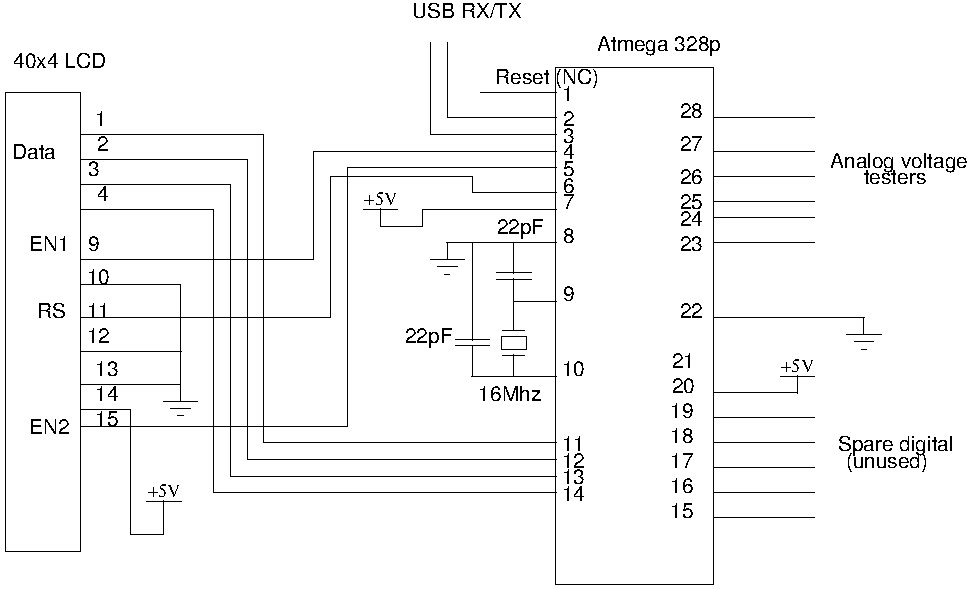
Drive a four-line LCD panel using an Arduino. The project initially aimed to control the LCD for displaying arbitrary information but evolved to include functionalities such as timekeeping, EEPROM read/write operations from the Atmel 328p, and voltage measurement. Multiple...
Applications include the 900 MHz ISM Band, Satellite TV LNB IF Amplifiers (950 - 2150 MHz), 1575 MHz GPS, 2.4 GHz ISM Band (802.11 b/g WLAN, Cordless, etc.), "SDARS" Satellite-based Radio (2.33 and 2.6 GHz), 5-6 GHz WLAN (802.11a),...
This project is designed to prevent unauthorized access to personal belongings left on a beach towel while swimming, and it can also be utilized in office or workshop settings. The circuit is compact and can be powered by simple...
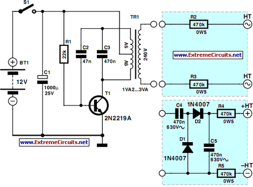
This DC voltage doubler circuit generates a voltage that is double the input supply voltage. It is beneficial when a higher voltage is required from a single lower voltage power source, particularly in applications with low current consumption. The DC...

AVR has two different programming modes called Parallel Programming Mode (Parallel Mode) and Serial Downloading Mode (ISP mode). In Parallel Mode, the programming is done using multiple data lines simultaneously, allowing for faster programming speeds. This mode is typically...
This is a power supply circuit that produces a voltage range of 12 to 24 V. It is straightforward, requiring only a bridge rectifier, a filter capacitor, and a transformer, without the need for a regulator. A bridge rectifier...