
Mini High-Voltage Generator

The circuit operates on the principle of a Hartley oscillator, which is a type of LC oscillator that utilizes inductive feedback to generate oscillations. In this design, the transistor acts as a switch that alternately allows current to flow through the primary winding of the center-tapped transformer, creating a magnetic field. As the magnetic field collapses, it induces a voltage in the secondary winding, which is then stepped up to a high voltage. The use of a center-tapped transformer is critical in this application as it provides a means to create the necessary feedback for oscillation.
The resistors R2 and R3 play a vital role in limiting the current to safe levels, ensuring that the circuit remains safe for the user while still delivering a sufficiently high voltage to deter unauthorized access. The inclusion of the voltage doubler circuit, which typically consists of additional diodes and capacitors, allows for further voltage enhancement, doubling the output voltage and increasing the deterrent effect.
For practical applications, careful attention must be paid to the placement of the metallic areas to ensure that they are easily accessible to potential intruders while remaining inconspicuous. This design not only serves its intended purpose but also provides an educational experience for those interested in electronics, particularly in understanding oscillator circuits and high-voltage generation. Proper safety precautions should always be observed when working with high voltages to prevent accidental shocks.Here`s a project that could be useful this summer on the beach, to stop anyone touching your things left on your beach towel while you`ve gone swimming; you might equally well use it at the office or workshop when you go back to work. In a very small space, and powered by simple primary cells or rechargeable batteries, the proposed circuit generat
es a low-energy, high voltage of the order of around 200 to 400 V, harmless to humans, of course, but still able to give a quite nasty poke` to anyone who touches it. Quite apart from this practical aspect, this project will also prove instructional for younger hobbyists, enabling them to discover a circuit that all the oldies` who`ve worked in radio, and having enjoyed valve technology in particular, are bound to be familiar with.
As the circuit diagram shows, the project is extremely simple, as it contains only a single active element, and then it`s only a fairly ordinary transistor. As shown here, it operates as a low-frequency oscillator, making it possible to convert the battery`s DC voltage into an AC voltage that can be stepped up via the transformer.
Using a centre-tapped transformer as here makes it possible to build a Hartley` oscillator around transistor T1, which as we have indicated above was used a great deal in radio in that distant era when valves reigned supreme and these was no sign of silicon taking over and turning most electronics into solid state`. The Hartley` is one of a number of L-C oscillator designs that made it to eternal fame and was named after its invertor, Ralph V.
L Hartley (1888-1970). For such an oscillator to work and produce a proper sinewave output, the position of the intermediate tap on the winding used had to be carefully chosen to ensure the proper step-down (voltage reduction) ratio. Here the step-down is obtained inductively. Here, optimum inductive tapping is not possible since we are using a standard, off-the-shelf transformer.
However we`re in luck ” as its position in the centre of the winding creates too much feedback, it ensures that the oscillator will always start reliably. However, the excess feedback means that it doesn`t generate sinewaves; indeed, far from it. But that`s not important for this sort of application, and the transformer copes very well with it. The output voltage may be used directly, via the two current-limiting resistors R2 an R3, which must not under any circum-stances be omitted or modified, as they are what make the circuit safe.
You will then get around 200 V peak-to-peak, which is already quite unpleasant to touch. But you can also use a voltage doubler, shown at the bottom right of the figure, which will then produce around 300 V, even more unpleasant to touch. Here too of course, the resistors, now know as R4 and R5, must always be present. The circuit only consumes around a few tens of mA, regardless of whether it is warding off` someone or not!
If you have to use it for long periods, we would however recommend powering it from AAA size Ni-MH batteries in groups of ten in a suitable holder, in order not to ruin you buying dry batteries. If you build the version without the voltage doubler and measure the output voltage with your multimeter, you`ll see a lower value than stated.
This is due to the fact that the waveform is a long way from being a sinewave, and multimeters have trouble interpreting its RMS (root-mean-square) value. However, if you have access to an oscilloscope capable of handling a few hundred volts on its input, you`ll be able to see the true values as stated.
If you`re still not convinced, all you need do is touch the output terminals. To use this project to protect the handle of your beach bag or your attachecase, for example, all you need do is fix to this two small metallic areas, quite close together, each connected to one output terminal of the circuit. Arrange them in such a way that unwanted hands are bound to touch both of them together; the result is guaranteed!
Just take care to avoid getting caught in your own trap when you take your bag to turn the circuit off! 🔗 External reference
Related Circuits
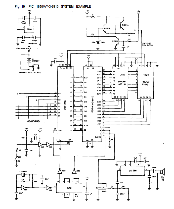
The AY-3-8910/8912 is a register oriented Programmable Sound Generator (PSG). Communication between the processor and the PSG is based on the concept of memory-mapped I/O. Control commands are issued to the PSG by writing to 16 memory-mapped registers. Each...
The 555 Stepper Pulse Generator kit will help you with the pulse required to drive your favorite DC Servo Motor application. This kit uses the famous 555 timer IC for generating the Stepping Pulse. More: Input - 5 -...
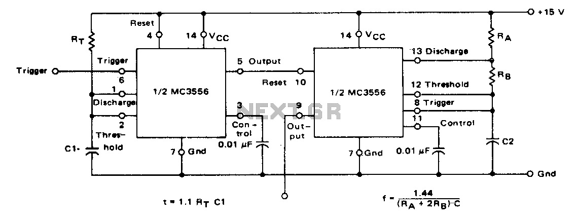
The first timer is used as a monostable and determines the tone duration when triggered by a positive pulse at pin 6. The second timer is enabled by the high output of the monostable. It is connected as an...

A basic square wave generator has been designed to operate a speedometer circuit board, which is responsible for controlling various functions. The square wave generator circuit typically consists of a few key components: a timer IC, such as the 555...

Generating sine waves with controlled frequencies over a wide range is challenging when using RC or LC sinusoidal oscillators. However, this can be effectively achieved using a wideband digital square wave oscillator, a counter, and a weighted summing network....
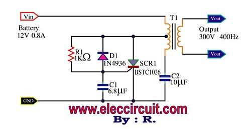
This is a Mini Power Inverter that utilizes SCR as the main electronic component. It operates an oscillator generator at 400Hz, providing an output of 300V from a 12V input voltage. The Mini Power Inverter is designed to convert a...