
Voltage splitter using Op-Amp

The voltage splitter circuit utilizing the uA741 operational amplifier (op-amp) is designed to provide a stable output voltage that is a fraction of the input voltage. The uA741 is a versatile, general-purpose op-amp known for its ease of use and reliability in various applications, including voltage splitting.
In a typical configuration, the voltage splitter employs a non-inverting op-amp setup. The input voltage is applied to the non-inverting terminal of the uA741, while a voltage divider network is created using two resistors connected to the inverting terminal. The values of these resistors determine the output voltage level. The feedback loop from the output to the inverting terminal ensures that the op-amp maintains the desired voltage level at the output.
For example, if resistors R1 and R2 are used in the voltage divider, the output voltage (Vout) can be expressed as:
Vout = Vin * (R2 / (R1 + R2))
Where Vin is the input voltage. This equation illustrates how the output voltage is a scaled version of the input voltage based on the resistor values.
The circuit diagram typically includes the uA741 op-amp, power supply connections, input voltage source, and the resistor network. Proper bypass capacitors should also be included near the power supply pins of the op-amp to filter out noise and ensure stable operation.
This voltage splitter circuit can be utilized in various applications where a specific lower voltage is required from a higher voltage source, such as in sensor applications, signal conditioning, and interfacing with microcontrollers. The uA741 op-amp’s characteristics, including its gain bandwidth product and input/output impedance, make it suitable for these types of applications, providing reliable performance and accuracy.Voltage splitter using op-amp uA741 IC, circuit diagram, working, description.. 🔗 External reference
Related Circuits
The advanced credit card, referred to as the "microcontroller super card," incorporates numerous innovative enhancements. The initial step involved verifying the code and subsequently uploading it to the Arduino board. The developed code enabled a counter to increment from...

The days of arriving home at night and entering into darkness are finally over. This is a highly practical device, and it has been designed as a module. This device is intended to provide illumination upon entering a dark space,...
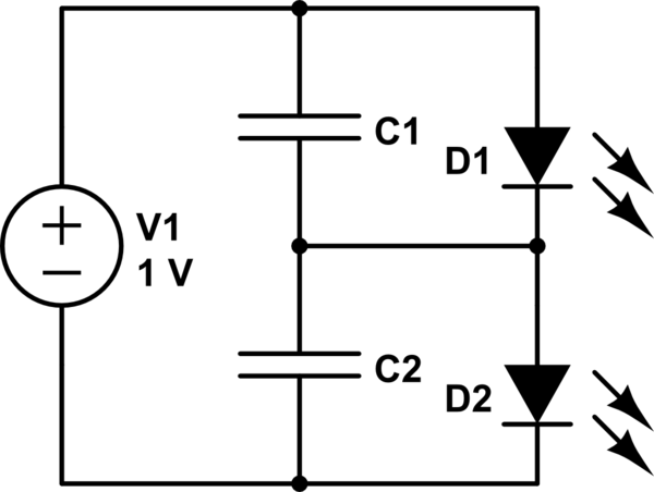
The first option is a Zener diode. There are several 2.2V Zener diodes available that could adequately protect the capacitor. However, a significant drawback is that half the energy may be wasted across the diode short. The question arises...
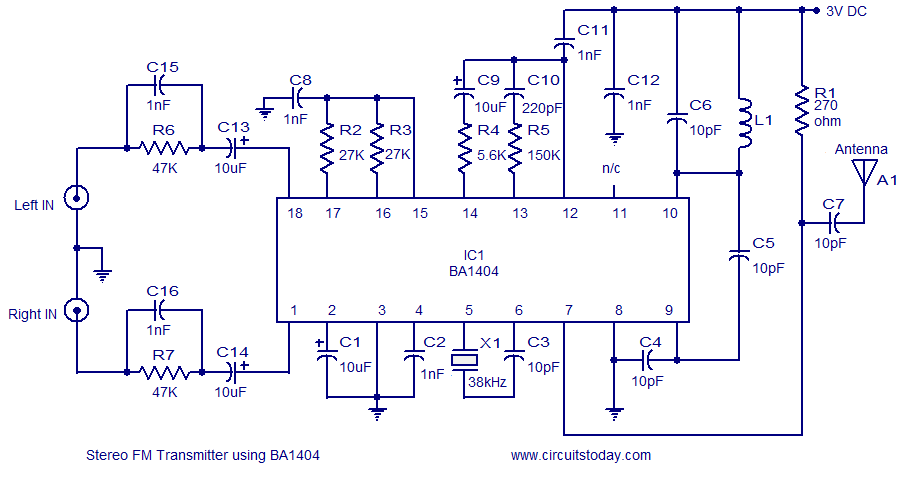
A high-quality stereo FM transmitter circuit is presented. This circuit utilizes the BA1404 integrated circuit from ROHM Semiconductors. The BA1404 is a monolithic FM stereo modulator that incorporates a stereo modulator, FM modulator, and RF amplifier circuitry. The FM...
This beeper circuit utilizes two 555 integrated circuits (ICs) and can operate within a supply voltage range of 5 to 15V DC. It is suitable for applications requiring an alarm or beeping signal. The first IC (IC1) is configured...
For relatively small projects with fewer pins than the ATmega328, the ATtiny series, specifically the ATtiny45 or ATtiny85, is a good choice due to its compact physical size. The ATtiny series microcontrollers, particularly the ATtiny45 and ATtiny85, are designed for...