
Voltmeter To Frequency Meter Using 4528

The frequency-to-voltage converter (FVC) circuit is a critical component in various applications, particularly in speed measurement and monitoring systems. The design typically consists of three primary functional blocks: the squarer, the voltage converter, and the output stage.
The squarer block is responsible for transforming the incoming frequency signal into a square wave. This transformation is essential because many subsequent processing stages in the circuit require a clean, square wave input for accurate operation. The squarer is designed to handle high input voltages, specifically up to 400V, which makes it suitable for industrial applications where such voltages are common. The capacitor C1 must be appropriately rated to ensure safe operation at these voltage levels, preventing damage to the circuit.
Following the squarer, the next block is the frequency-to-voltage conversion stage. This stage takes the square wave output and converts it into a proportional voltage. The output voltage corresponds to the frequency of the input signal, allowing for easy measurement and interpretation. This block may utilize operational amplifiers and other analog components to achieve precise voltage conversion, ensuring that the output is linear and accurately reflects the input frequency.
The final block is the output stage, which can be configured to provide either a digital or analog output. For digital applications, the output may be fed into a microcontroller or digital display, while for analog applications, it may drive a standard analog meter or other devices that require a voltage input. The design of the output stage will depend on the specific requirements of the application, including the desired output range and the load characteristics.
Overall, the frequency-to-voltage converter circuit is a versatile tool in electronic measurement systems, providing a reliable means of converting frequency signals into usable voltage levels for further processing or display. Proper component selection, particularly for high-voltage applications, is essential to ensure the longevity and accuracy of the circuit.Normally we often encountered the frequency meter can be used in speed sensor, tachometer, measurement or signal recurring. This frequency to voltage converter (FVC) can be used to change the voltage into a digital or analog tachometer.
Circuit that consists of three blocks. The first block is squarer, the input signal to a square wave. This block is protected from high input voltage up to 400V, but remember this only works if the value of capacitor C1 is for 400V 🔗 External reference
Related Circuits
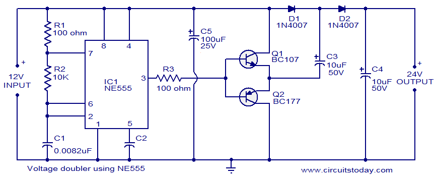
The circuit diagram of a simple voltage doubler using the NE555 timer is presented. In this configuration, the NE555 IC operates as an astable multivibrator at approximately 9 kHz. The bases of two transistors, Q1 and Q2, are connected...
A user has recently purchased the Dantimax that mic preamp and is seeking guidance on how to install a VU meter. The integration of a VU meter with the Dantimax mic preamp can enhance audio monitoring by providing visual feedback...
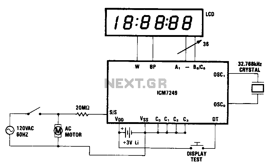
In this application, the ICM7249 is configured as an hours-in-use meter that displays the total number of whole hours of line voltage applied. The 20-MD resistor and high-pass filtering enable AC line activation of the SIS input. This configuration,...
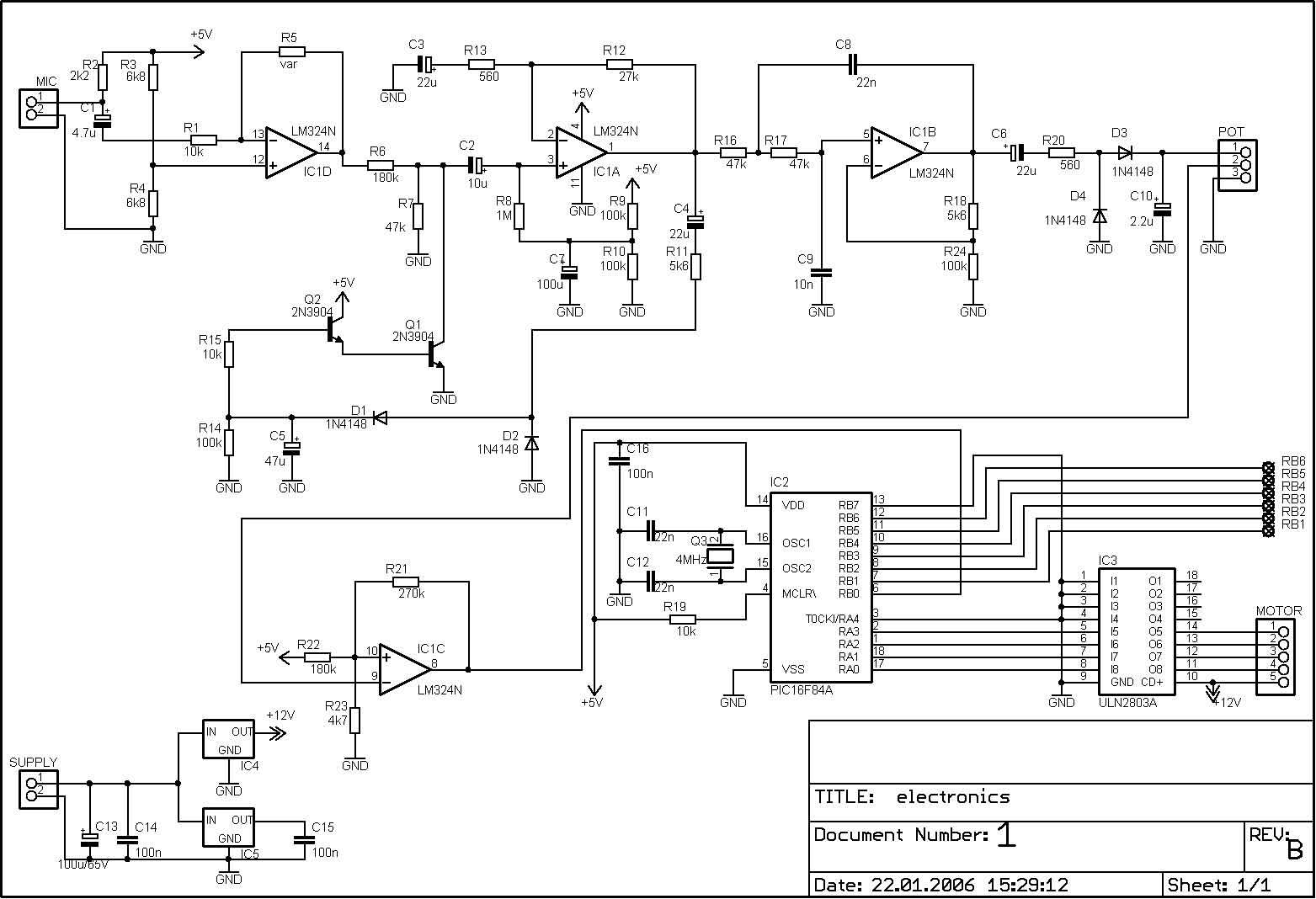
The PIC microcontroller is capable of controlling a motor after each beat, with the option to bypass certain beats using pushbuttons. The rotation speed and duration can also be adjusted within specified limits to prevent register overflow or underflow....
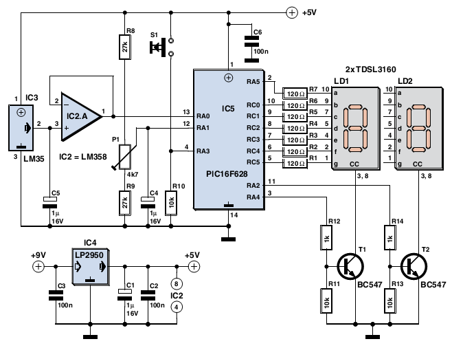
The device is user-friendly and consumes minimal current, allowing it to operate throughout the battery's shelf life. It employs a standard LM35DZ sensor (IC3) whose analog output voltage is buffered by an LM358 (IC2A). The voltage is processed by...
The circuit exhibits a flat frequency response ranging from approximately 20Hz to over 50kHz. The input sensitivity is set at 100mV for full-scale deflection on a 100µA meter. It is constructed using two common emitter amplifiers; the first stage...