
Voltmeter With LED For Car Battery

The described comparator circuit is designed to accurately measure and indicate the voltage level of a car battery in increments of one volt. It utilizes a voltage comparator, which is a device that compares two input voltages and outputs a digital signal based on their relative magnitudes.
The circuit typically consists of a reference voltage source, which establishes the threshold levels for the comparison, and the car battery voltage is fed into one of the comparator's inputs. The other input is connected to the reference voltage, which can be set at intervals corresponding to the voltage levels of interest (e.g., 0V, 1V, 2V, etc.).
When the voltage from the car battery exceeds the reference voltage, the comparator outputs a high signal, indicating that the battery voltage is above the set threshold. Conversely, if the battery voltage is below the reference level, the output will be low. This output can be connected to an LED indicator or an LCD display to provide a visual representation of the battery voltage level.
For enhanced functionality, multiple comparators can be used in a ladder configuration to cover a wider voltage range. Each comparator can be set to a different reference voltage, allowing for a more granular indication of the battery's state. Additionally, hysteresis can be introduced into the circuit to prevent rapid toggling of the output due to minor fluctuations in battery voltage.
Power supply considerations are crucial for the comparator circuit; it should operate within the voltage rating of the components used, ensuring reliable performance. Furthermore, proper filtering and protection measures should be implemented to safeguard the circuit from voltage spikes or noise that may be present in automotive environments.
Overall, this comparator circuit serves as an effective solution for monitoring the voltage of a car battery, providing clear and immediate feedback on its state of charge.Below is a comparator circuit which is can measure with step of 1 volt, the voltage of car battery. The indication of voltage is done by comparison of? . 🔗 External reference
Related Circuits

This voltmeter ammeter is designed to measure output voltage ranging from 0-70V to 0-500V with a resolution of 100mV and can measure current from 0-10A or more with a resolution of 10mA. It is an ideal addition to any...
The bi-directional sequencer employs a 4-bit binary up/down counter (CD4516) and two "1 of 8 line decoders" (74HC138 or 74HCT138) to produce the widely recognized Nigh. The bi-directional sequencer circuit is designed to manage the sequencing of outputs based on...
The analog to digital sketches have been extensively covered using various components. To progress to more complex circuits and concepts, it is essential to understand these simpler ones. This tutorial will not delve as deeply as others due to...
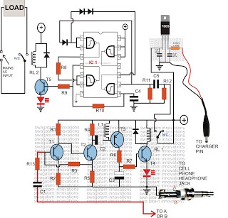
Control any electrical device from anywhere in the world using a cell phone, without incurring costs for individual commands. This system allows operation of various appliances, such as vehicles, doors, and air conditioners, with a simple button press on...
These circuits provide a means of altering the YELLOW output of RED / GREEN type two colour light emitting diodes. These circuits use the LM555 timer chip. The circuit described utilizes the LM555 timer integrated circuit (IC) to modulate the...
The circuit is a comparator that can measure the voltage of a car battery in steps of 1 Volt. The voltage is determined after comparing the voltage of the battery, which is applied to the inverting inputs of amplifiers,...