
Colour Shifting LED`s

The circuit described utilizes the LM555 timer integrated circuit (IC) to modulate the output of two-color light-emitting diodes (LEDs) that can emit red and green light, producing a yellow output when both colors are combined. The LM555 timer can be configured in various modes, such as astable, monostable, or bistable, depending on the desired effect for altering the YELLOW output.
In a typical configuration, the LM555 timer is set up in astable mode to create a pulse-width modulation (PWM) signal. This PWM signal can control the brightness of the red and green LEDs, allowing for a dynamic range of yellow shades. The frequency and duty cycle of the PWM can be adjusted by selecting appropriate resistor and capacitor values connected to the LM555 timer.
For instance, to achieve a desired frequency, resistors R1 and R2, along with capacitor C1, are chosen based on the formula for the frequency of an astable circuit:
\[ f = \frac{1.44}{(R1 + 2R2) \cdot C1} \]
The duty cycle, which determines the ratio of the "on" time to the total cycle time, can be modified by varying the values of R1 and R2. A higher duty cycle will result in a brighter yellow output, while a lower duty cycle will dim the output.
The output of the LM555 timer can be connected to a transistor or a MOSFET to drive the LED load, ensuring that the current and voltage ratings of the LEDs are not exceeded. This arrangement allows for efficient control over the LED operation while providing sufficient current to achieve the desired brightness.
This circuit can be used in various applications, including decorative lighting, indicators, and displays, where the ability to control the color output dynamically is advantageous. Proper thermal management should be considered to prevent overheating of the LEDs during prolonged operation.These circuits provide a means of altering the YELLOW output of RED / GREEN type two colour light emitting diodes. These circuits use the LM555 timer chip. 🔗 External reference
Related Circuits
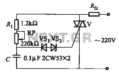
The introduction for a unidirectional thyristor trigger circuit is also applicable to the TRIAC. Several bidirectional circuits are illustrated in Figure 16-28. Figures 16-28 (a) and (b) depict a direct trigger circuit; Figure 16-28 (c) illustrates a dual diode...
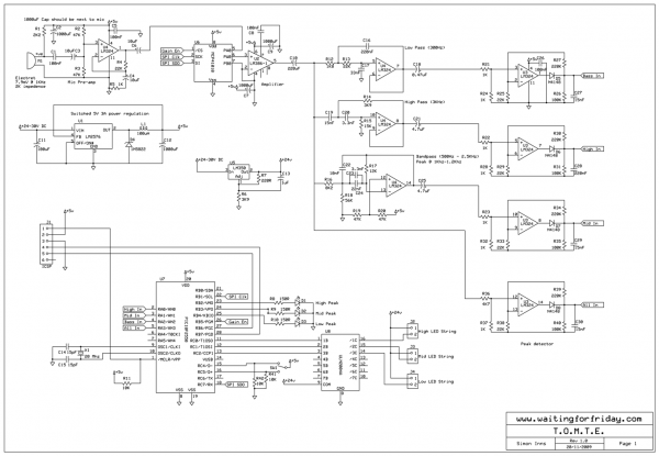
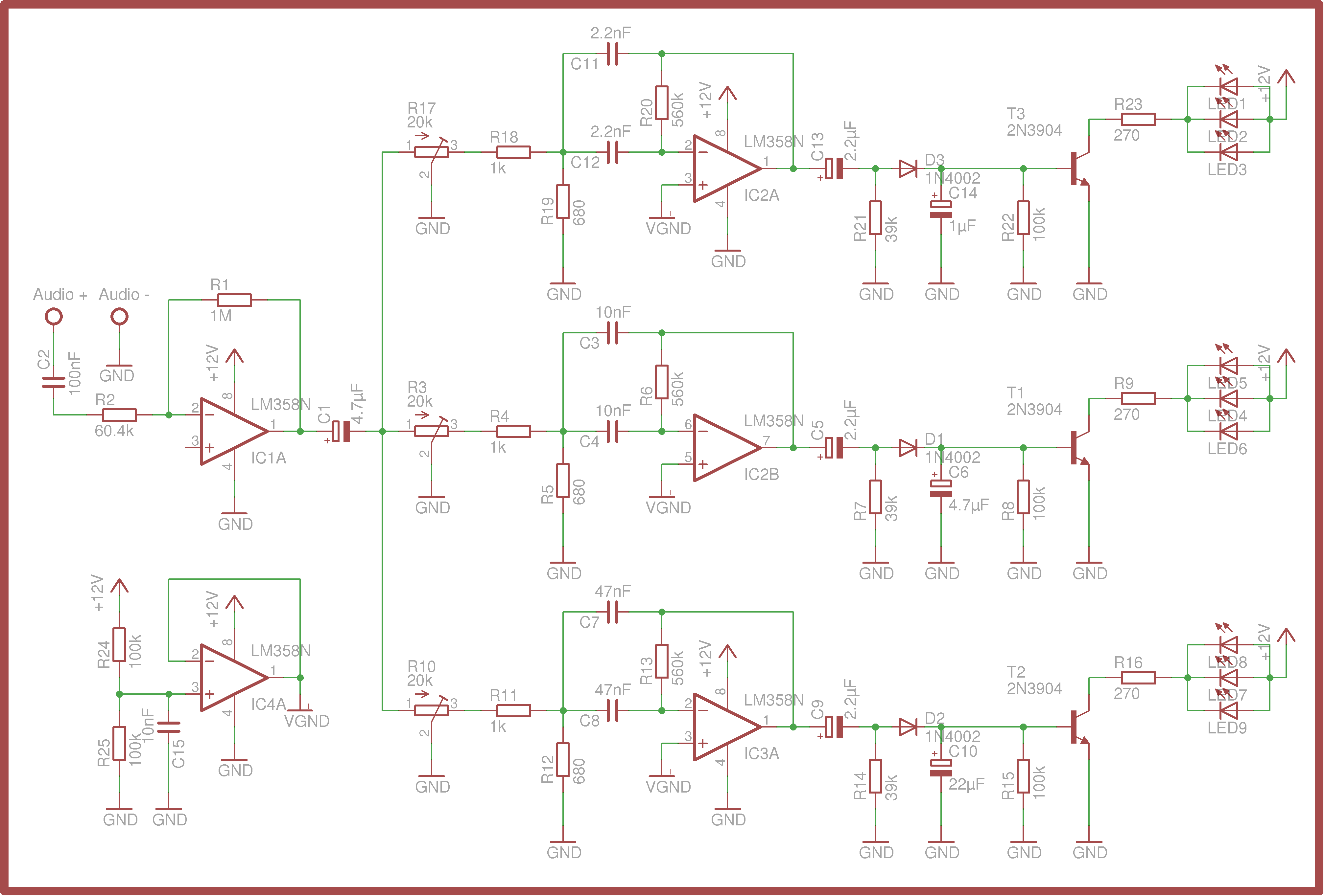
Most existing designs utilize direct switching of lights without any software control and include manual potentiometers for light sensitivity and overall gain settings. There are limited references regarding the frequency filter circuitry, explaining the specific frequencies the circuit is...
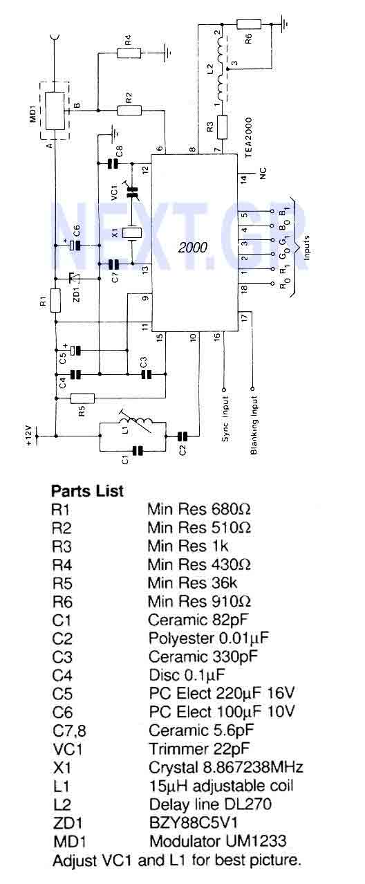
A PAL color encoder and video summer which requires just composite sync and composite blanking inputs, and a 6-bit binary coded input giving the color information. The inputs are organized as 2 bits per primary color with gamma correction...
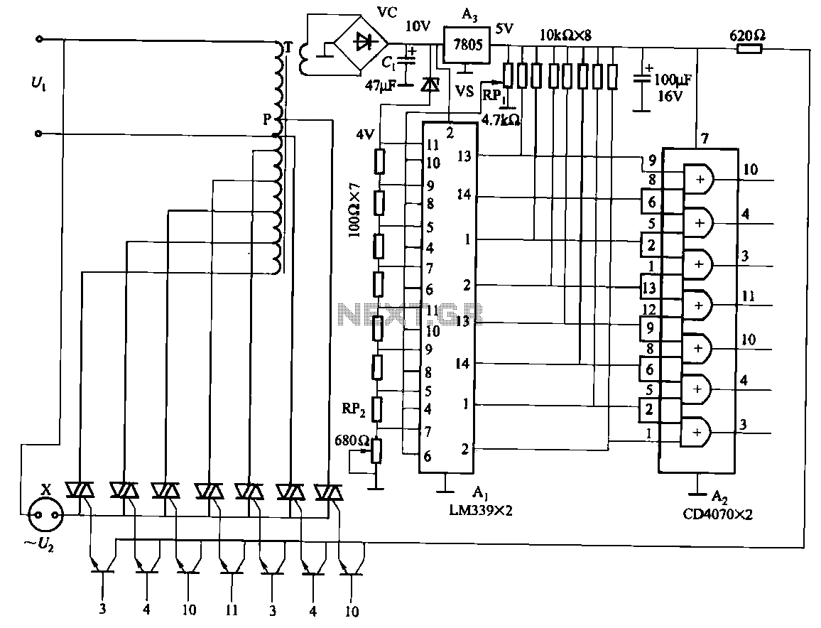
The circuit consists of two LM339 comparators and two CD4070 XOR gate thyristors, along with additional components such as an autotransformer exchange regulator. It also features overvoltage and undervoltage protection. The control range can be adjusted by modifying the...
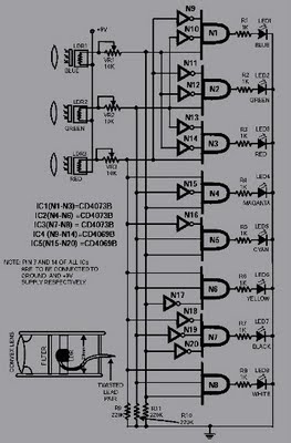
This circuit is capable of sensing eight colors: blue, green, and red (primary colors); magenta, yellow, and cyan (secondary colors); along with black and white. It is designed based on the principles of optics and digital electronics. The object...
Colour Organ Videos complete instructions for this episode of Weekend Projects can be found. Fifteen years ago, a box was acquired from an uncle. Here is what it does. The Colour Organ is an electronic device designed to produce visual...