
Voltmeter with LED for car battery PCB

The described circuit utilizes a comparator configuration to effectively monitor the voltage levels of a car battery. The comparator operates by comparing the input voltage from the battery with reference voltages derived from a Zener diode, which is known for its ability to maintain a stable voltage output across varying temperatures and load conditions. This stability is crucial for accurate voltage measurements.
The circuit design incorporates an adjustable resistor (RV1) that allows the user to set a specific voltage threshold. By rotating the variable resistor, the reference voltage level can be modified, enabling the circuit to be calibrated for different battery types or conditions. This feature enhances the versatility of the circuit, making it suitable for various automotive applications.
The output of the comparator is visually indicated through four LEDs, which light up in response to the battery voltage level. Each LED corresponds to a specific voltage range, providing a clear and intuitive visual representation of the battery's state. This setup allows for quick assessment of the battery condition without the need for additional measuring equipment.
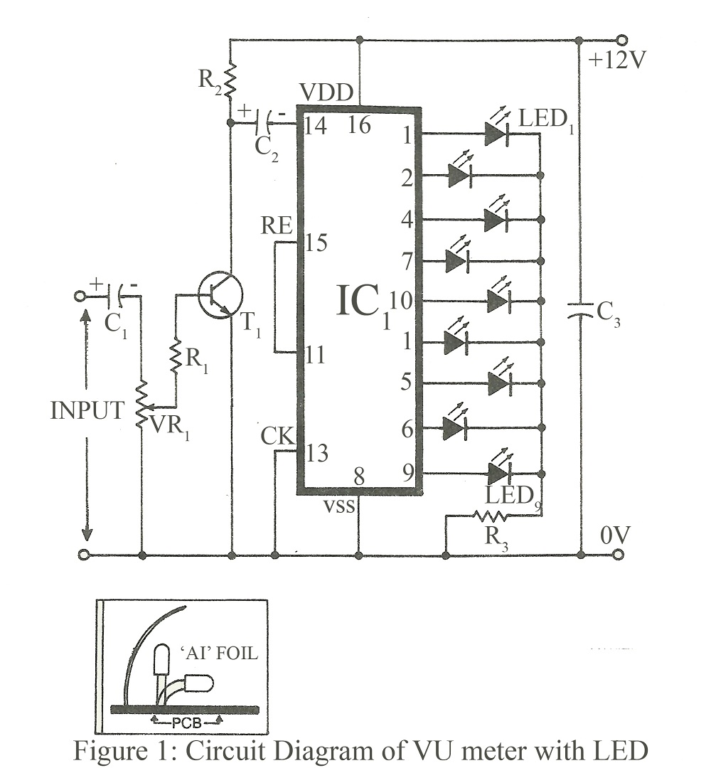
Overall, the circuit's design emphasizes simplicity, reliability, and user adjustability, making it an effective tool for monitoring car battery voltage in real-time. Proper selection of the Zener diode and careful calibration of RV1 are essential for ensuring accurate performance and longevity of the circuit.The circuit, is a comparator, can measure with step of 1Volt, the voltage of battery of car. The clue of voltage become after comparison of voltage of battery, that is applied in the inverting inputs of amplifiers, with voltages of reference that are produced by a Zener D1, the value of which is such so that it present good thermic stability. With the RV1, we regulate the gradation of voltage that we want. The optical clue become from four Led. 🔗 External reference
Related Circuits
When constructing a stereo amplifier or if one is already owned, it is beneficial to incorporate this circuit. The entire setup is based on the IC4017, with its clock input connected through a BC107 transistor. The IC4017 functions as...
This is an improved version of the audio interface commonly used to connect a computer soundcard to a transceiver's receive and transmit audio circuits. This kind of interface is used by computer programs that send and receive SSTV, RTTY,...
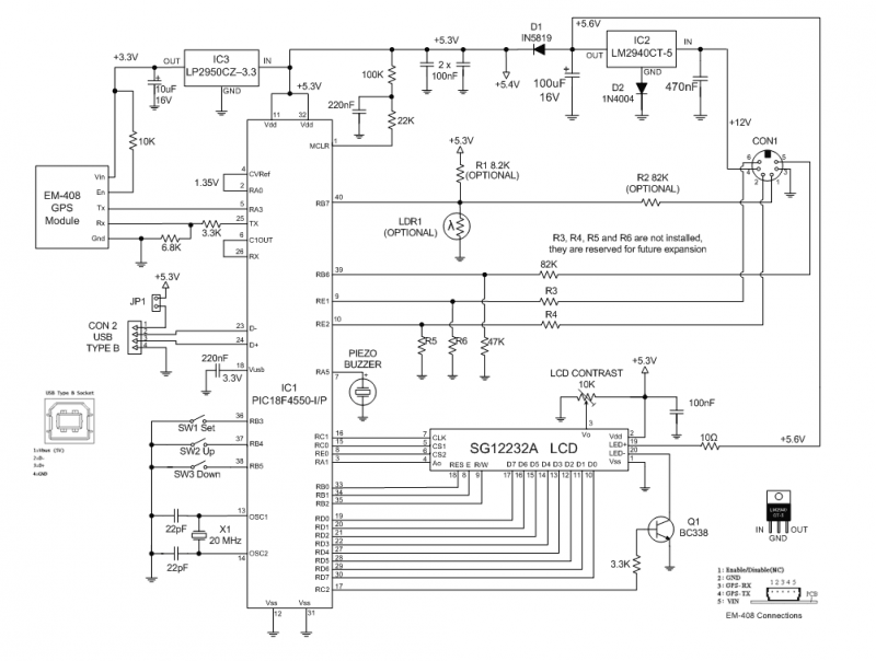
The GPS Car or Boat Computer is capable of displaying a variety of GPS-related information for enthusiasts of driving or boating. This page contains all the necessary information to construct the unit, including design specifications, schematic diagrams, parts list,...
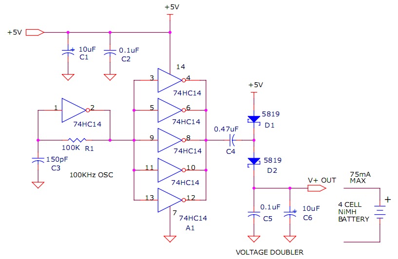
The circuit described will trickle charge a four-cell pack of AA or AAA NiMH batteries. It draws current from the +5V available from a USB connection and supplies approximately 70mA of current to the battery. This current level is...
The use of diode rectifiers in AC voltmeters with a low lower limit of measurement range (0.5-1 V) leads to significant nonlinearity of the scale due to the nonlinearity of the current-voltage characteristics of diodes. The incorporation of electronic...
A switch that is controlled by its ambient temperature operates without human intervention, except during the assembly of the electronic thermostat. This thermally controlled switch has numerous practical applications. For instance, if the internal temperature of a computer rises...