
vu meter with led

The circuit design utilizes the IC4017, a decade counter integrated circuit, which counts the input pulses received at its clock pin. This input is derived from a sound signal processed through a BC107 transistor, which acts as a switch to control the clock input based on audio levels. The IC4017 has ten output pins, each corresponding to a count from zero to nine. When the sound level increases, the transistor allows more frequent pulses to reach the clock input, thus incrementing the count and illuminating the corresponding LED.
For stereo applications, two IC4017 circuits are employed in tandem, ensuring that each channel of the amplifier is visually represented. The output from the main speakers is tapped for input, allowing the circuit to respond dynamically to the audio signals. Calibration of the circuit is achieved through the VR1 variable resistor, which can be adjusted to fine-tune the sensitivity of the LEDs to the audio input.
In configurations where fewer LEDs are desired, a connection from the output of one LED to the reset pin (pin 15) of the IC4017 can be utilized to manage the LED count effectively. It is crucial to ensure that pin 12 remains unconnected, as it does not serve a function in this application.
The visual representation of sound through the LED indicators enhances the overall experience of the audio system. By orienting a second LED towards the audience, the effect of the sound-to-light response is amplified, creating a more engaging atmosphere. This circuit not only adds a decorative element to the stereo amplifier but also provides a visual cue to the dynamics of the music being played.If you are making a stereo amplifier, or if you own one already, then do not hesitate to add this circuit. The entire circuit is wired around IC4017 whose clock input is tapped through transistor BC107. Basically, IC 4017 is a 1-of-10 decade counter or a decoder. To suggest the design, this circuit fills the gap between a simple 1-transistor sound -to-light and a unit using filter and main LEDs. But two units must be added for stereo operation. Circuit calibration is straight forward and should present no problem. The effect of sound reaching the input is to trigger IC to count one. This means that when the music gets louder, the LEDs move faster. If you wish to use fewer LEDs, a wire must link from the next LED and should go on to reset pin 15. Note that pin 12 doesnot have any connection. To tap the input to this circuit, it is advised to tap the output from the main speakers. VU Meter with LED If the LEDs do not move rapidly according to the music pitch, adjust VR1. If two LEDs are in parallel, the second one can be pointed towards the viewer for added effect. 🔗 External reference
Related Circuits
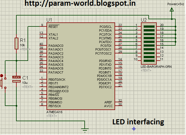
The circuit interfaces an LED with an AVR microcontroller (ATMega16). The components used include one ATMega16 microcontroller, a 10K resistor, a 16uF/25V capacitor, a push button switch, and a green LED bar instead of eight individual LEDs. The power...
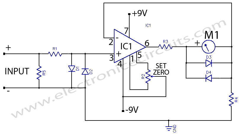
The microampere meter provides full-scale deflection for a 0.1 V input. The current to be measured flows through a known resistor. The microampere meter is an essential instrument used for measuring very low currents in the microampere range. It operates...
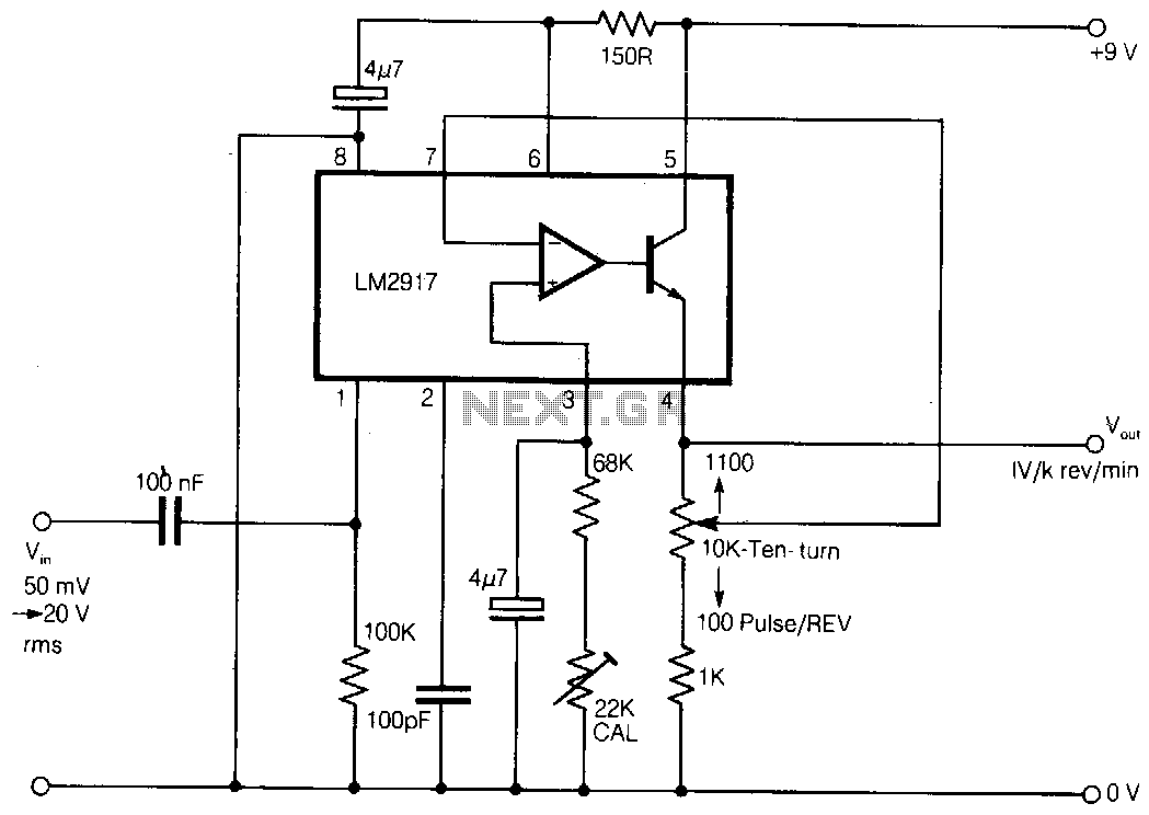
Here is a simple tachometer circuit for use with a hand-held DVM or portable chart recorder. A novel feature is that the source frequency pulse/rev rate can be directly set on a ten-turn potentiometer to provide a convenient calibration...
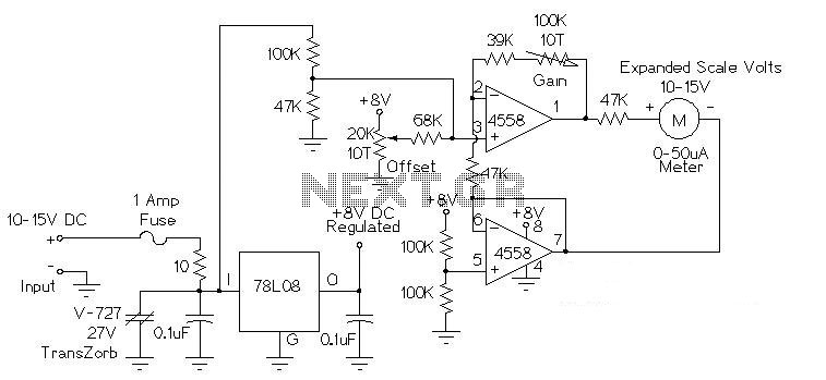
This circuit is used to measure the voltage on a 12V (nominal) lead acid rechargeable battery system. It was specifically designed for use in solar powered systems, but is general enough that it can be used for automotive or...
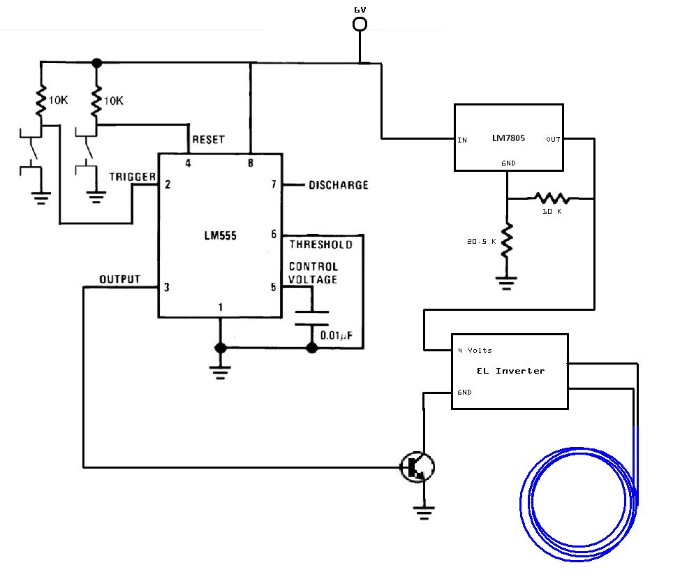
The circuit utilized for this project is quite simple. Some may criticize the omission of decoupling capacitors for the LM7805 voltage regulator. The circuit in question employs the LM7805 voltage regulator, which is designed to provide a stable output voltage...
The LM555 timer IC can be utilized in various electronic projects, including the creation of an analog timer. According to the datasheet, the LM555 is versatile and can be adjusted to set timers based on specific requirements. The schematic...