
Volume Control Circuit Schematic using DS 1669 Potentiometer IC

The digital volume control circuit employs the DS1669 integrated circuit, which functions as a digital potentiometer. The DS1669 is designed to provide precise control over resistance, allowing for accurate volume adjustments in audio applications. The circuit typically consists of a microcontroller that interfaces with the DS1669, sending digital signals that dictate the desired resistance level.
The DS1669 features a series of terminals: two for connecting the power supply, one for the wiper output, and two for the fixed resistors. The wiper output can be connected directly to the audio signal path, enabling the adjustment of the signal amplitude based on the selected resistance.
In practical applications, the circuit can be connected to an audio amplifier, where the output from the DS1669 adjusts the input signal level. This setup allows for smooth volume changes without introducing noise or distortion, making it ideal for high-fidelity audio systems.
The control interface can be designed using buttons or a rotary encoder, providing user-friendly volume adjustment. Additionally, the circuit may incorporate feedback mechanisms to ensure the volume level is displayed accurately, enhancing user experience.
Overall, the digital volume control circuit using the DS1669 is a versatile solution for modern audio systems, offering reliability and precision in volume management.A digital volume control circuit diagram using DS 1669, a potentiometer IC.This can be used as a digital volume controller for audio amplifiers and other applications.. 🔗 External reference
Related Circuits
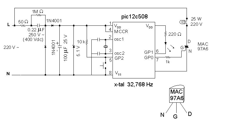
Introduction It is time for the 8-pin microcontroller Microchip PIC12C508, the SAVER V3.2, a new design of a device that controls a night light by turning it on and off. The SAVER V3.2 utilizes the Microchip PIC12C508 microcontroller, which features...
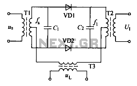
A balanced diode mixer circuit is presented, utilizing two diodes, specifically the 2AP9 model. The circuit operates with a high voltage, causing the diodes to function in an off state, which is also referred to as a diode switch...
It is entirely feasible and acceptable to control various outputs while sitting at a PC terminal. A simple hardware circuit and software are utilized to interface with a 7-segment rolling display. The printer port of a PC provides a...
This circuit provides a digital square wave that can be viewed directly or used to drive other circuits. It used the CMOS 4047 Low-Power Monostable/Astable Multivibrator. As used in Tom Duncan's Adventures with Digital Electronics Book, to drive CMOS...
A transistor optocoupler interface circuit, as described in section 15.1.6, has been implemented. This circuit serves as a transistor interface with other circuits. The transistor optocoupler interface circuit utilizes a light-emitting diode (LED) and a phototransistor to achieve electrical isolation...
This design is for an interpolating scanner, a circuit featuring multiple signal inputs, a control voltage input, and a signal output. The output selectively transitions between inputs, smoothly fading from one to the next as the control voltage increases....