
VOX Circuit

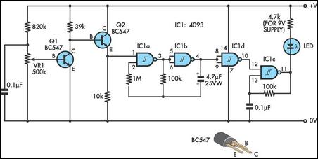
The VOX circuit operates as a voice-activated switch, utilizing a combination of transistors, resistors, capacitors, and diodes to achieve its functionality. The input signal is first processed through the volume potentiometer, which sets the desired activation threshold. When the audio signal exceeds this threshold (typically around 600mV), it triggers the base of transistor T1, allowing current to flow. The role of resistor R3 is critical as it ensures that excessive input voltages do not damage T1 by limiting the base current.
Diode D1 serves a protective function by clamping the input signal, ensuring that the voltage across the emitter-base junction (Veb) of T1 does not drop below 0.6V. This helps maintain the transistor in an active state when necessary and prevents false triggering from noise or low-level signals.
The Darlington pair configuration of T2 amplifies the current to drive the relay, which serves as the output actuator of the VOX circuit. Resistor R4 plays an essential role in keeping the relay deactivated when T1 is not conducting, ensuring that the circuit remains stable during idle periods. The use of capacitor C2 in the circuit allows for filtering, smoothing out any fluctuations in the output signal, which is critical for maintaining consistent performance in audio applications.
Resistor R5 is strategically placed to limit the base current flowing into T2, providing an additional layer of protection against overcurrent conditions that could damage the transistor. The overall design of the VOX circuit ensures that it can handle a maximum input voltage of 40V, with a current consumption that can reach up to 100mA during overload conditions. This comprehensive design allows the VOX to function effectively in various audio equipment setups, providing reliable and responsive voice activation.VOX is a switch ordered by voice, often used at microphones instead of the classic switch button. The vox described here may be connected to almost any type of audio equipment which has an external speaker for coupling. The threshold action is set with volume potentiometer of the audio amplifier which commands the VOX. The signal (on speakerphone) from the terminals of R2 is connected capacitive on T1 base. Resistance R3 limits base current of the transistor, in cases in which voltage input exceeds 600mV. Diode D1 hangs positive trip of the input signal, so Veb can not become less than 0. 6V. Relay form the output circuit is ordered by Darlingtonul T2. Resistance R4 maintains the relay unoperated as long as T1 is blocked. The bipolar capacitor C2 allows to work as filter together with T2. Resistance R5 is limiting the T2 current base at a security level. The threshold of switching VOX`s is about 600mV (R2). Maximum input voltage is determined by maximum admissible dissipation on R2 and R3. As a rule entry tension should not exceed 40Vvv. VOX consumed current is primarily formed by the sum of relay coil currents and R5. At VOX`s overloading, the resistance may lead up to 100mA. 🔗 External reference
Related Circuits
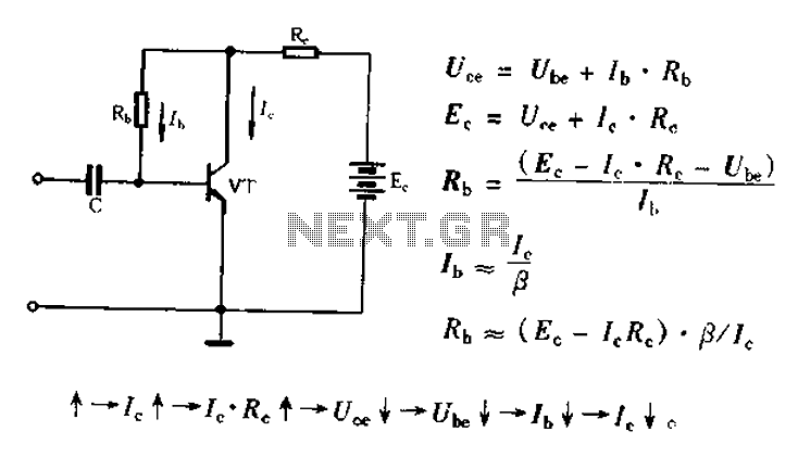
Bias voltage negative feedback circuit The bias voltage negative feedback circuit is a crucial component in various electronic applications, particularly in amplifiers and oscillators. This circuit is designed to stabilize the operating point of a transistor or operational amplifier by...
You may be familiar with this effect. You switch audio equipment such as an amplifier to a different input and there is a loud click or "thump" in the speaker system. Not all equipment is affected. Some high-end audio...
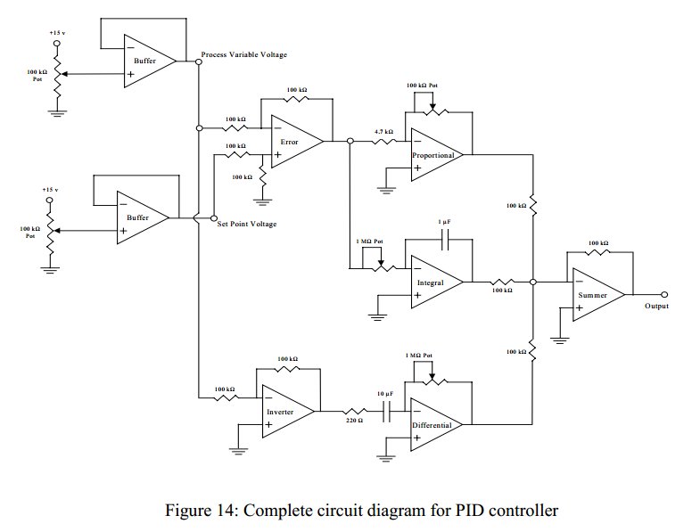
Convert a feedforward operational amplifier PID loop to C code. Assistance is needed for this conversion, as the process is unfamiliar. Input values can be obtained through an ADC, such as voltage or current, but coding a feedforward PID...
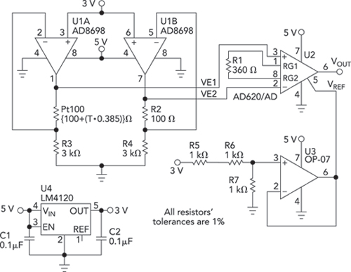
Bridge circuits are widely used for conditioning signals from resistive sensors. These circuits are sensitive to minor changes in resistance, providing a differential output from a single current or voltage source. However, the sensors connected to a passive bridge...
This design integrates power-on and low-battery indications, capable of operating with any battery voltage up to 15V. It features a very low current drain of 2mA or less and costs less than $3.50 with new components. When the battery...
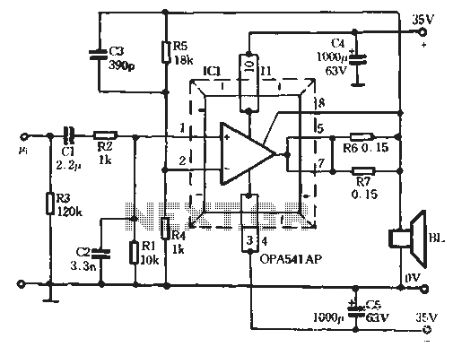
The Burr-Brown OPA541 chip is a power amplifier capable of operating with a maximum power supply voltage of 40V, delivering a continuous output current of up to 5A. The output current can be adjusted using an external resistor to...