
Warble Alarm Circuit

The circuit employs a dual timer configuration, leveraging the capabilities of the 556 timer, which contains two 555 timer circuits in a single package. The first timer is configured in astable mode, generating a continuous square wave output. The frequency of this output is primarily influenced by the resistors R1 and R2, as well as the capacitors C1 and C2. The relationship governing the frequency of oscillation can be described by the formula:
f = 1.44 / ((R1 + 2*R2) * C1)
where f represents the frequency in Hertz, R1 and R2 are the resistances in ohms, and C1 is the capacitance in farads.
The output from the first timer is then fed into the second timer, which is configured to modulate the square wave signal. This modulation results in the generation of two distinct frequencies, approximately 400 Hz and 500 Hz, which alternate to create a warbling effect. This is achieved by adjusting the values of R1, C1, R2, and C2, allowing for precise control over the output frequencies.
The circuit is typically powered by a DC voltage supply, which must be within the operating range of the 556 timer IC. To ensure reliability and stability, decoupling capacitors may be added to the power supply lines. Additionally, the output signal can be connected to a speaker or buzzer, which converts the electrical signals into audible sound, effectively producing the desired alarm tone.
Overall, the design is compact and can be implemented in various applications requiring an audible alarm, making it suitable for integration into emergency vehicle systems or other alert mechanisms. Proper selection of component values is critical for achieving the intended sound characteristics and ensuring optimal performance of the circuit. This circuit uses a 556 to first generate a low frequency square wave, that is modulated to produce two alternate tones of about 400 and 500 Hz. Circuit generates warble alarm of European emergency vehicles. The frequencies of the oscillators are determined by the values of Rl, CI and R2, C2.
Related Circuits
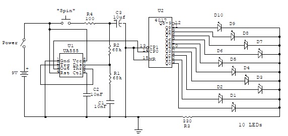
This electronic circuit is a simplified version of an electronic roulette game, utilizing the 4017 integrated circuit (IC), which functions as a 10-stage decade counter/divider. It is driven by a versatile 555 IC configured as a voltage-controlled oscillator (VCO)....
This circuit is an adjustable voltage reference circuit, which serves as a voltage source that provides a voltage greater than that of the reference diode. High precision applications that operate over an extended temperature range necessitate a restriction on...
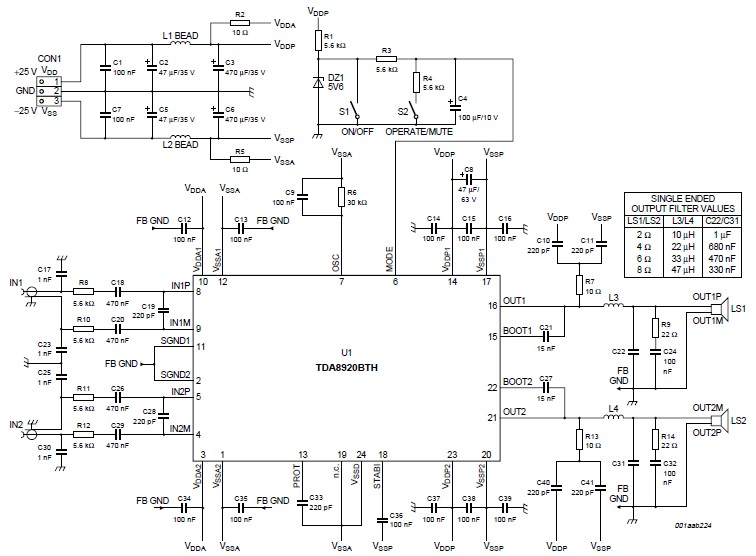
This high-power Class D audio amplifier electronic project is designed using the TDA8920BTH audio power amplifier IC. This power amplifier IC offers very high efficiency with minimal dissipation, yielding significant output power. The typical output power is 200 watts...
This box is a portable transfer standard to maintain and carry with you a local time signal of 59 short beeps (pips) plus a long 0.4 sec beeeeep on the full minute. At the start of the job, the...
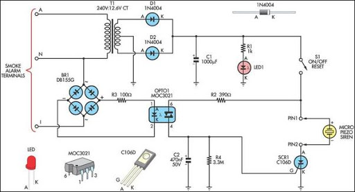
This alarm circuit is designed to monitor a mains-powered smoke detector located in a shed used for dog kennels. It ensures complete isolation from the mains, allowing low-voltage (12V) cabling to run to the alarm circuit, which is situated...

This is a Variable Voltage Regulator Circuit built using the LM317T integrated circuit (IC). The LM317T is an adjustable three-terminal positive voltage regulator capable of supplying more than 1.5 amps over an output range of 1.25 to 37 volts....