
variable voltage regulator circuit

The LM317T voltage regulator circuit is designed for versatility in various applications requiring adjustable output voltage. The circuit's functionality is primarily determined by the selection of resistors R1 and R2, which set the output voltage based on the specified formula. The use of a minimum load current is crucial for the stability and proper operation of the regulator, as it ensures that the device remains in regulation.
In practical applications, the choice of R1 and R2 values can be tailored to achieve the desired output voltage. For instance, if a specific output voltage is needed, one can calculate the required resistance values using the output voltage formula. The resistor R1 is typically chosen to be around 120 ohms to maintain the minimum load current, while R2 can be adjusted accordingly to achieve the desired output voltage.
The inclusion of capacitors in the circuit design is essential for enhancing performance. The output capacitor (1 µF tantalum or 25 µF electrolytic) improves the transient response, allowing the regulator to respond quickly to changes in load conditions. The input capacitor (0.1 µF tantalum) serves to filter out high-frequency noise, particularly when the regulator is located away from the power supply filter, ensuring stable operation.
To prevent damage from reverse voltage conditions during power-off scenarios, the addition of a diode across the input and output terminals is a prudent measure. This diode allows current to bypass the regulator, thereby protecting it from potential reverse voltage spikes.
It is also important to consider the transformer specifications when designing this circuit. The transformer must provide an input voltage that is sufficiently higher than the desired output voltage, taking into account the voltage drop across the regulator. A minimum of 3 volts above the output voltage is recommended to ensure reliable operation under full load conditions.
Overall, this LM317T-based variable voltage regulator circuit is a robust solution for applications requiring adjustable voltage, with features that enhance reliability and performance.This is a Variable Voltage Regulator Circuit that is built by LM317T IC. The LM317T is an adjustable 3 terminal positive voltage regulator capable of supplying in excess of 1. 5 amps over an output range of 1. 25 to 37 volts. The device also has built in current limiting and thermal shutdown which makes it essentially blow-out proof.
This circuit ca n be use to make a stable power supply. You can looks the circuit diagram from the figure. The principle work of the circuit is output voltage is set by two resistors R1 and R2 connected as shown below. The voltage across R1 is a constant 1. 25 volts and the adjustment terminal current is less than 100uA. The output voltage can be closely approximated from Vout=1. 25 * (1+(R2/R1) which ignores the adjustment terminal current but will be close if the current through R1 and R2 is many times greater.
A minimum load of about 10mA is required, so the value for R1 can be selected to drop 1. 25 volts at 10mA or 120 ohms. Something less than 120 ohms can be used to insure the minimum current is greater than 10mA. The example below shows a LM317 used as 13. 6 volt regulator. The 988 ohm resistor for R2 can be obtained with a standard 910 and 75 ohm in series. When power is shut off to the regulator the output voltage should fall faster than the input. In case it doesnt, a diode can be connected across the input/output terminals to protect the regulator from possible reverse voltages. A 1uF tantalum or 25uF electrolytic capacitor across the output improves transient response and a small 0.
1uF tantalum capacitor is recommended across the input if the regulator is located an appreciable distance from the power supply filter. The power transformer should be large enough so that the regulator input voltage remains 3 volts above the output at full load, or 16.
6 volts for a 13. 6 volt output. 🔗 External reference
Related Circuits
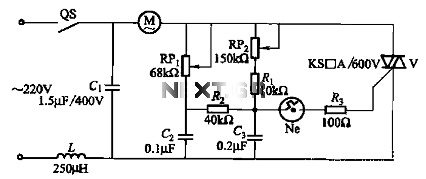
The 3P10 circuit, illustrated in the figure, utilizes a bidirectional thyristor for control. The adjustment potentiometer RPi allows for modification of the minimum motor speed, while the adjustment potentiometer RP2 enables continuous variation of the motor speed, reaching up...
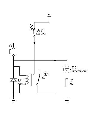
The circuit can also be triggered by logic ICs (TTL/CMOS) using the appropriate interfacing method. Another relay is typically used to serve as the trigger button when interfacing ICs with the latching relay circuit. The described circuit utilizes a latching...
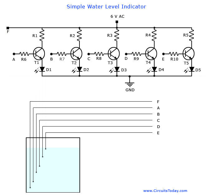
A simple water level indicator project with a circuit diagram for home and industry. This water tank level sensor can be utilized for any liquid level indicator projects. The water level indicator circuit is designed to monitor and display the...
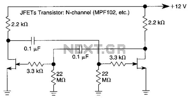
The use of JFETs allows for high resistance and long time constants in this very low frequency multivibrator. The values indicated are for operation at 0.15 Hz. In the context of electronic circuit design, a multivibrator is a circuit that...
Boiling water on a kitchen gas stove can lead to issues such as spilling boiling water if the process is not monitored, which can extinguish the flame and cause gas leakage. A notification device can address this problem. The...

Many brands in Asia utilize ultrasonic remote control switch circuits, with some employing relays and others utilizing thyristors. The remote control transmitter is of a puffer type, featuring an ultrasound flute with both olive and flat circular shapes. This...