
water alarm schematic

The LM1830 fluid detector IC is a specialized component intended for fluid detection applications. It operates at higher voltage levels, making it less suitable for battery-powered devices. Its design is focused on accuracy and reliability in fluid detection, but this comes at a higher cost and power consumption.
In contrast, the 74HC14 CMOS IC provides a more versatile and power-efficient alternative. Its lower operating voltage and minimal current draw make it particularly advantageous for battery-operated devices. The architecture of the 74HC14 includes six inverters, each able to function with hysteresis, which helps stabilize the input signal against noise and fluctuations.
The circuit design incorporates a feedback mechanism through resistor R1 and the water sensor, creating a reliable square wave signal generator. This configuration not only enhances the performance of the inverter but also ensures that the system remains stable and responsive. Resistor R2 plays a critical role in maintaining the input signal level, preventing oscillations that could lead to unnecessary power consumption.
The piezo buzzer is driven by the remaining inverters, providing an audible alarm signal when fluid presence is detected. Capacitor C2 is strategically placed to block DC current during monitoring, thus preserving battery life and ensuring efficient operation. This design exemplifies a balance between functionality and power efficiency, making it suitable for various fluid detection applications, particularly in portable or battery-powered devices.The LM1830 fluid detector IC from National Semiconduc tor is designed to be able to detect the presence of fluids using a probe. This chip requires a relatively high supply voltage and is not the most frugal power consumer. It is also quite specialised so unless you are buying in bulk the one-off price is not cheap. An alternative circuit show n h er e uses a standard CMOS IC type 74HC14. It has the advantage of operating with a 3 V supply and consumes less than 1 µA when the alarm is not sounding, this makes it ideal for use with batteries. The 74HC14 has six inverters with hysteresis on their input switching thresholds. A capacitor (C1) and a feedback resistor (R1) is all that`s necessary to make an inverter into a square wave signal generator.
In the water alarm circuit the feedback resistor consists of R1 and the water sensor in series. R1 prevents any possibility of short-circuit between the inverter`s input and out-put. Resistor R2 defines the inverter`s input signal level when the sensor is not in water. Any open-circuit (floating) input can cause the inverter to oscillate and draw more current. The remaining inverters in the package (IC1. B to IC1. F) drive the piezo buzzer to produce an alarm signal. Capacitor C2 ensures that no DC current flows when the circuit is in monitoring mode (with the alarm silent) this helps reduce the supply current. 🔗 External reference
Related Circuits

Pyroelectric Fire Alarm System Diagram. The front end of the circuit contains a sensitive signal amplifier constructed close to IC1 (CA3130). It delivers a high output when the temperature near the piezo component raises. IC CA3130 is a CMOS...

The CMOS 4001 consists of four independent two-input NOR gates. These gates are organized into two pairs. Gates 1 and 2 are connected to form a latching circuit. When the alarm is triggered, they will latch and activate the...
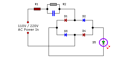
Compact yet highly functional, this is a straightforward and efficient LED circuit designed to operate directly from the AC mains supply, ranging from 100 volts to 230 volts. This LED circuit utilizes a few essential components to achieve efficient...
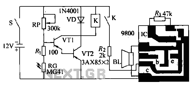
Boiling water or cooking with a gas stove can sometimes lead to the fire being extinguished due to water spills, which can result in a significant gas overflow and pose a risk of poisoning. This example describes a stall...
Save fuel bills and the economy of the planet with this circuit. SW1 is a normally open press button switch which allows you to view the level of hot water in a hot water tank. When pressed the voltage...
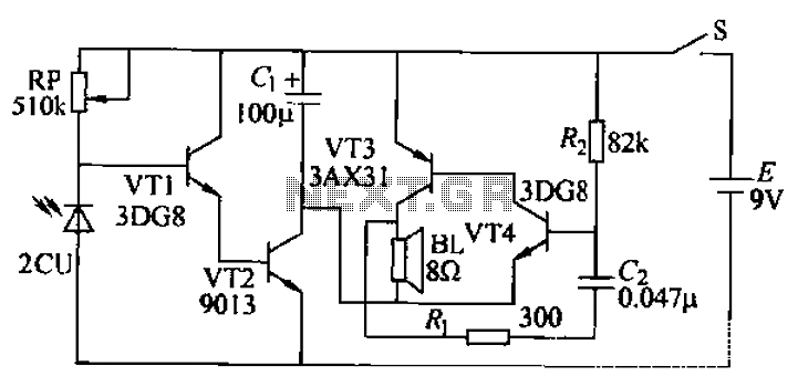
The circuit presented is a second-generation flame alarm for natural gas stoves. After the gas stove is ignited and normal combustion occurs, the power switch S is closed. The photoresistor RG, influenced by the light from the flame, has...